Putting into operation, 1 checks, 2 connecting – Memmert INCO 246/246 med CO2 Incubators (Generation 2003) User Manual
Page 24
24
Putting into Operation
4.
Putting into Operation
4.1
Checks
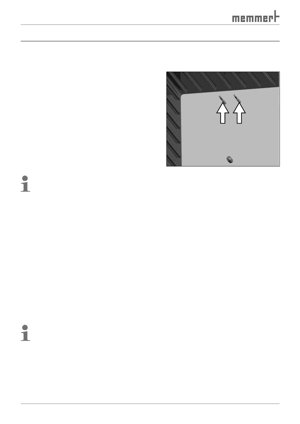
4.1.1 Checking the temperature sensor
Especially strong vibrations during transport could
result in the temperature sensors being moved
in their holders in the working chamber.
Check the temperature sensor for its correct
positioning and if necessary adjust its position
in the holder ( Fig. 10 ).
4.1.2 Check the door and adjust if
necessary
See page 64 .
4.2
Connecting
4.2.1 Power supply
Caution:
Observe the country-specific regula-
tions when making connections (e. g. in Germany DIN VDE 0100 with residual current
device / RCD). Observe the connection and power ratings (see nameplate).
The incubator is intended for operation on an electrical power system with a system imped-
ance Z
max
at the point of transfer (service line) of a maximum of 0.292 ohms. The operator
must ensure that the incubator is operated only on an electrical power system that meets
these requirements. If necessary, you can ask your local energy supply company what the
system impedance is.
Connect power cable (see Fig. 4 on page 13 ).
4.2.2 External devices
(only for models with communication or premium modules)
Only appliances whose interfaces comply with the requirements for safety extra-low voltge
(e.g. PC, laptop, printer) may be connected to the connections on the rear of the incubator
(see Fig. 4 on page 13 ). Which devices may be connected depends on the chosen model /
module variant ( Communication interfaces described in detail from page 58 ).
4.2.3 Water connection
(only for models with humidity module)
Only use distilled water or DI water.
1. Fill up the supplied water supply tank (canister) with distilled water and place behind/
next to the incubator.
2. Attach the supplied hose the quick-release connections to the canister and the water sup-
ply "H
2
O“ on the rear of the appliance (see Fig. 4 on page 13 ).
Fig. 10
Temperature sensor