3 node address (node id), Node address (node id), System bus (can) for lenze plc devices – Lenze DDS System bus CAN for PLC User Manual
Page 77: Configuration (can−aux interface)
System bus (CAN) for Lenze PLC devices
Configuration (CAN−AUX interface)
6−3
l
PLC−Systembus EN 2.0
6.3
Node address (Node ID)
Assign a node address − also called Node ID − within the range of 1 to 63 to each node within the
system bus network as a definite identification.
·
The same node address may not be assigned more than once within the network.
·
The configuration of the node address for the CAN−AUX interface of the PLC is effected via
code C2450:
Code
LCD
Possible settings
Information
Lenze
Selection
C2450 CAN1 address
1
1
{1}
63 System bus node address
·
Save changes with C0003 = 1.
·
Changes are only valid after
reset node!
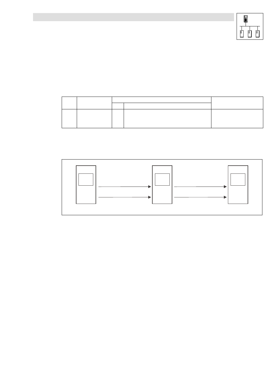
Allocation of the node address for the data exchange among Lenze devices
If Lenze devices are provided with node addresses in a consistent ascending order, the identifiers
of the event−controlled data objects (CANaux2_IO/CANaux3_IO) are set in way by the factory which
enables a communication from one device to the other:
L
Node-ID 1
FIF-CAN2_OUT
FIF-CAN2_IN
FIF-CAN3_OUT
FIF-CAN3_IN
L
Node-ID 2
FIF-CAN2_OUT
FIF-CAN2_IN
FIF-CAN3_OUT
FIF-CAN3_IN
L
Node-ID 3
Fig. 6−1
Data exchange among Lenze devices