7 transmitting parameter data, 1 parameter data telegram, Transmitting parameter data – Lenze DDS System bus CAN for PLC User Manual
Page 23: Parameter data telegram, Pter 2.7, System bus (can) for lenze plc devices, General information, 1 identifier
System bus (CAN) for Lenze PLC devices
General information
2−11
l
PLC−Systembus EN 2.0
2.7
Transmitting parameter data
For Lenze devices, parameter data are the so−called codes.
·
Parameter settings for instance are carried out in the case of a one−time setting of the system
during commissioning, or in the case of a material change of the production machine.
·
Parameter data are transferred as so−called SDOs (Service Data Objects) via the system bus
and are acknowledged by the receiver, i. e. the transmitter receives a feedback on whether the
transmission was successful.
2.7.1
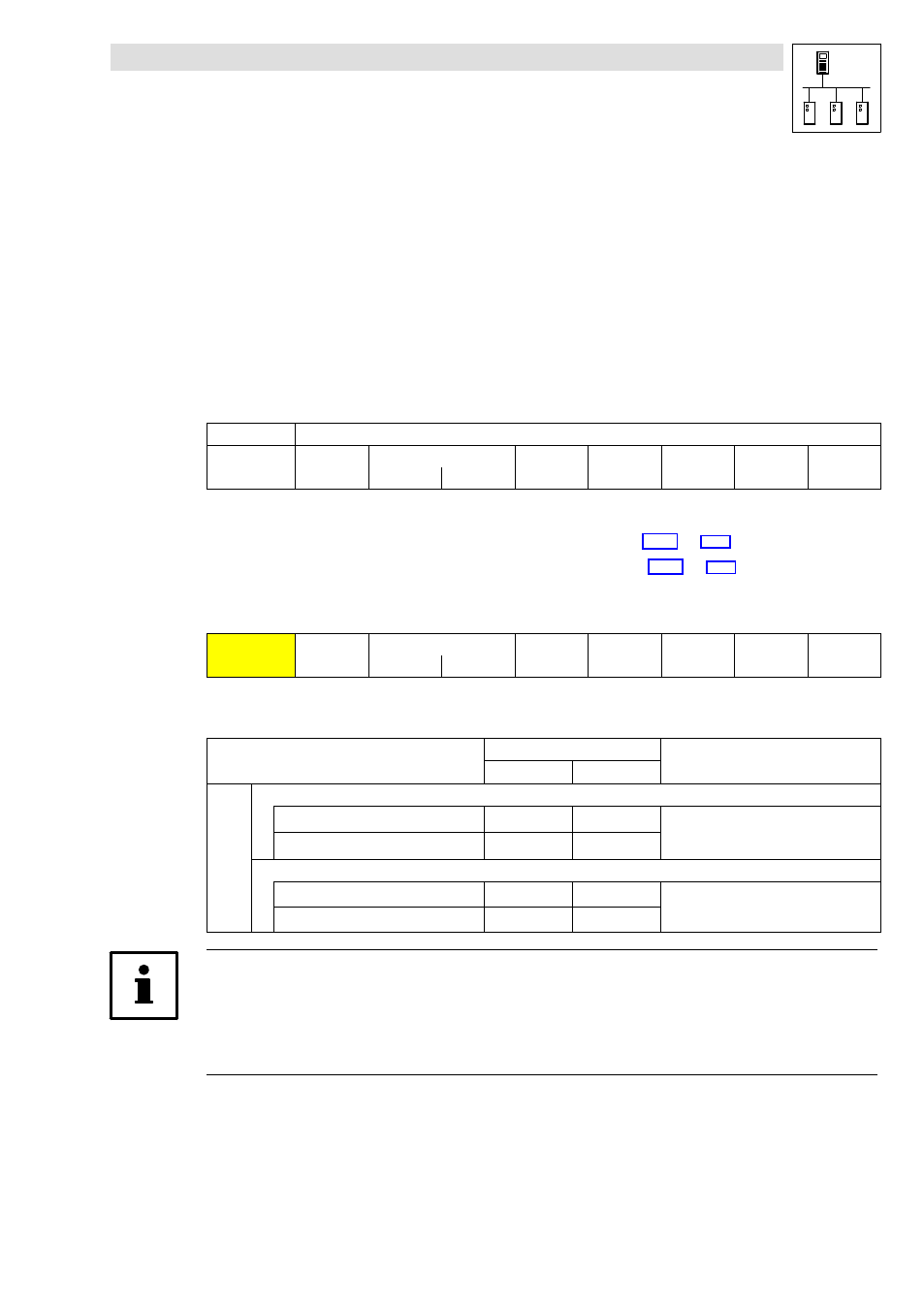
Parameter data telegram
The telegram for parameter data is structured as follows:
11bit
8 bytes user data
Identifier
Command
code
Index
Subindex
Data 1
Data 2
Data 3
Data 4
Low byte
High byte
·
In the following subchapters the different components of the telegram are explained in detail.
·
An example for writing a parameter can be found in chapter 2.7.2.
(
·
An example for reading a parameter can be found in chapter 2.7.3.
(
^ 2−17)
2.7.1.1
Identifier
Identifier
Command
code
Index
Subindex
Data 1
Data 2
Data 3
Data 4
Low byte
High byte
For the transmission of parameter data, two parameter data channels are provided, which are
addressed via the identifier:
Identifier =
basic identifier
+ node address of the node
dec
hex
SDOs
Parameter data channel 1
Output (transmission)
1536
600
+ C0350
+ C2350
+ C2450
(CAN)
(XCAN)
(FIF−CAN/CANaux)
Input (reception)
1408
580
Parameter data channel 2
Output (transmission)
1600
640
+ C0350
+ C2350
+ C2450
(CAN)
(XCAN)
(FIF−CAN/CANaux)
Input (reception)
1472
5C0
Tip!
Between the identifiers for parameter data channels 1 and 2 there respectively is an offset of 64:
·
Output of parameter data channel 1 = 1536
·
Output of parameter data channel 2 = 1536 + 64 = 1600