System bus (can) for lenze plc devices, General information, 2 command code – Lenze DDS System bus CAN for PLC User Manual
Page 24
System bus (CAN) for Lenze PLC devices
General information
2−12
l
PLC−Systembus EN 2.0
2.7.1.2
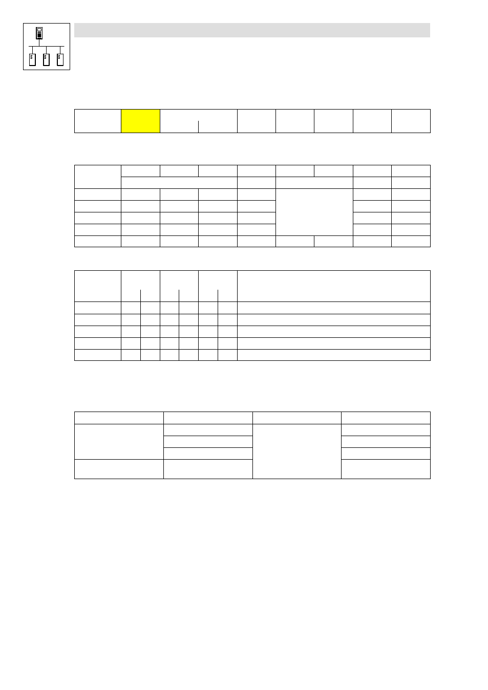
Command code
Identifier
Command
code
Index
Subindex
Data 1
Data 2
Data 3
Data 4
Low byte
High byte
Among other things, the command code contains the command to be carried out as well as
information on the parameter data length, and is structured as follows:
Bit 7 (MSB)
Bit 6
Bit 5
Bit 4
Bit 3
Bit 2
Bit 1
Bit 0
Command
Command Specifier (cs)
Length
e
s
Write request
0
0
1
0
00 = 4 bytes
01 = 3 bytes
10 = 2 bytes
11 = 1 byte
1
1
Write response
0
1
1
0
0
0
Read request
0
1
0
0
0
0
Read response
0
1
0
0
1
1
Error Response
1
0
0
0
0
0
0
0
Command code for parameters with 1, 2, or 4 bytes data length:
4 byte data
(32 bit)
2 byte data
(16 bit)
1 byte data
(8 bit)
Command
hex
dec
hex
dec
hex
dec
Information
Write Request
23
35
2B
43
2F
47
Send parameter to a node
Write Response
60
96
60
64
60
96
Node response to "write request" (acknowledgement)
Read Request
40
64
40
64
40
64
Request for reading a parameter of a node
Read Response
43
67
4B
75
4F
79
Response to the read request with an actual value
Error Response
80
128
80
128
80
128
Node reports an error with regard to communication
"Error Response" command
In the case of this error, an "Error Response" is generated by the node that is addressed.
·
This telegram in data 4 always contains the value "6", and in data 3 an error code:
Error Response command code
Data 3
Data 4
Error message
80
hex
3
6
Access denied
5
Incorrect subindex
6
Incorrect index
C0
hex
8
Job was not edited
(for 8200 vector + FIF module)