System bus (can) for lenze plc devices, Can system blocks – Lenze DDS System bus CAN for PLC User Manual
Page 113
System bus (CAN) for Lenze PLC devices
CAN system blocks
7.7
CAN_Synchronization (node number: 102)
7−25
L
PLC−Systembus EN 2.0
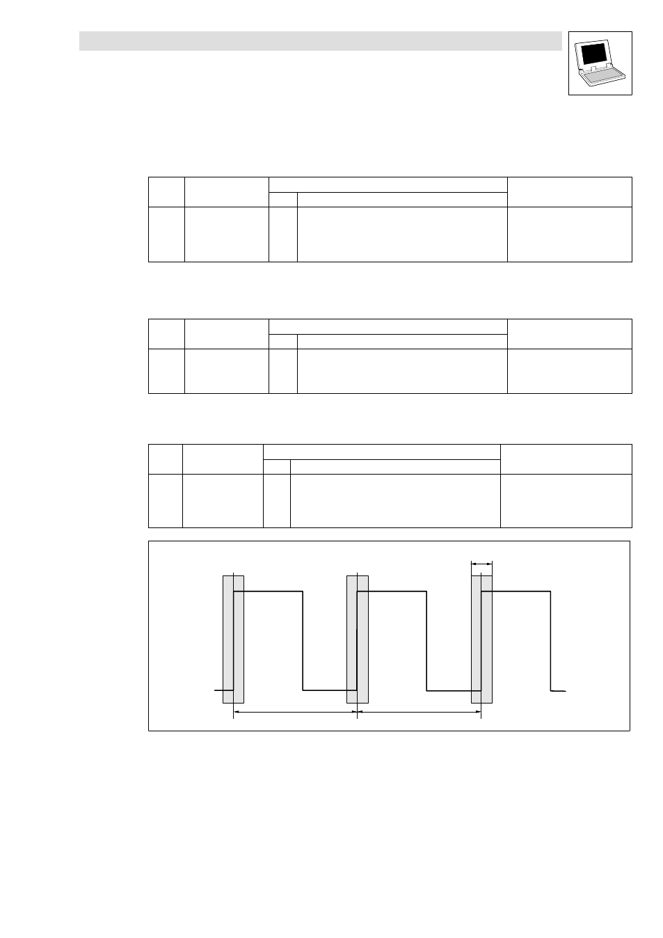
Synchronisation cycle
The controllers/PLCs receive the sync telegram/signal and compare the time between two
LOW−HIGH edges of the signal to the specified cycle time (C1121).
Code
LCD
Possible settings
IMPORTANT
Lenze
Selection
[C1121] Sync cycle
2
1
{1 ms}
13 Synchronisation cycle
Definition of the cycle time of the
sync telegram/signal.
·
Parameterisation is only
required for the slave!
·
The value set in C1121 is the time between two sync telegrams/signals of the master.
Phase displacement
Code
LCD
Possible settings
IMPORTANT
Lenze
Selection
[C1122] Sync phase
0.460
0
{0.001 ms}
6.5 Synchronisation phase
Phase shift between the sync
telegram/signal and the start of the
internal control program.
Monitoring the synchronisation (time slot)
The variable CAN_bSyncInsideWindow_b can be used for monitoring the synchronisation.
Code
LCD
Possible settings
IMPORTANT
Lenze Selection
[C1123] Sync window
0
0
{0.001 ms}
6.5 Synchronisation window
If the sync telegram/signal sent by
the master is in this "time slot",
CAN_bSyncInsideWindow_b
switches to TRUE.
Sync signal
Sync window
SyncCycle
SyncCycle
Fig. 7−8
"Time slot" for the LOW−HIGH edges of the sync signal