13 diagnostics, 1 operating status of the can interface, Operating status of the can interface – Lenze DDS System bus CAN for PLC User Manual
Page 47: System bus (can) for lenze plc devices, Can" system bus interface configuration
System bus (CAN) for Lenze PLC devices
"CAN" system bus interface configuration
3−13
l
PLC−Systembus EN 2.0
3.13
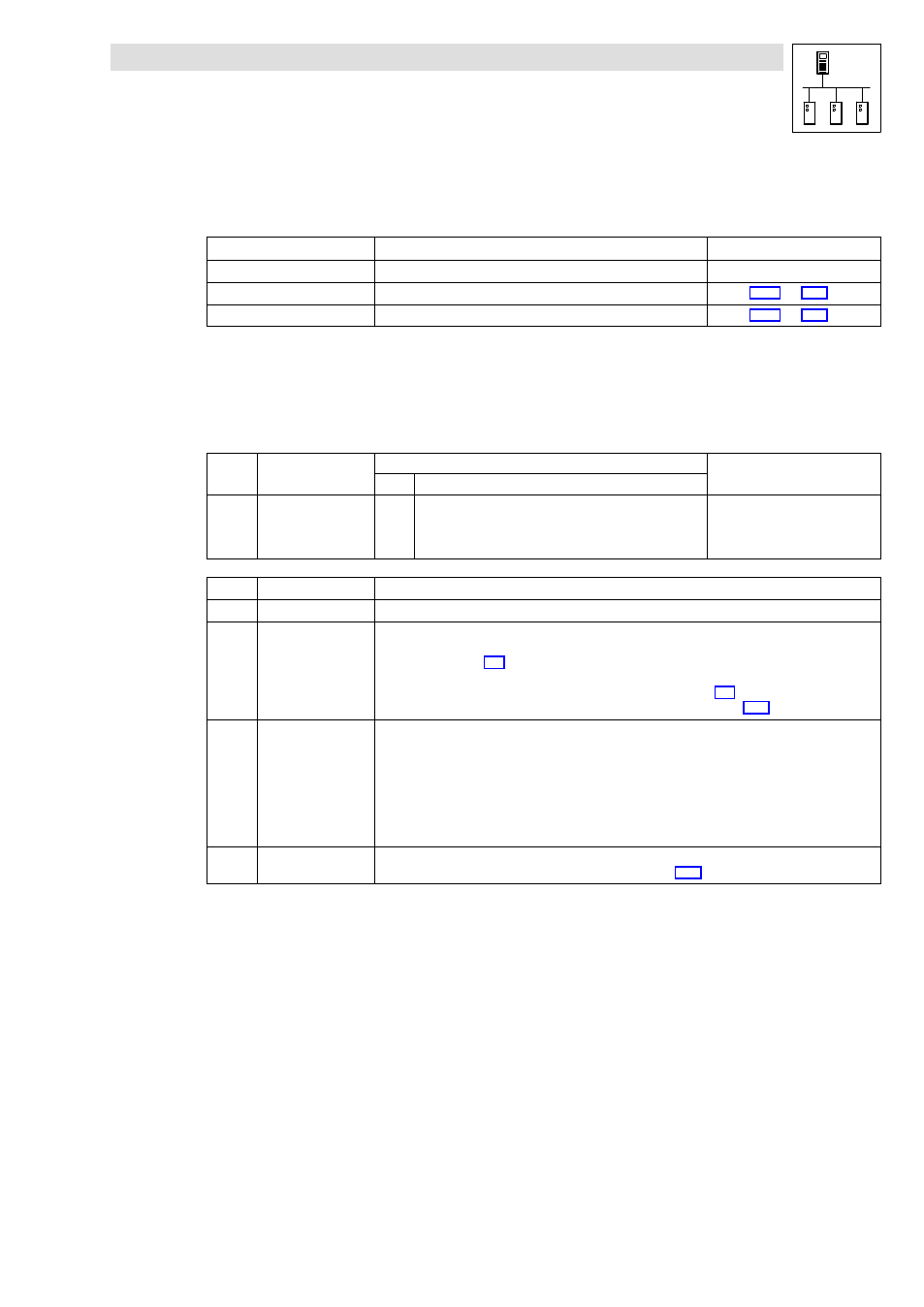
Diagnostics
The following codes can be used for diagnostics purposes:
Code
Information displayed
Information
C0359
Operating status of the system bus
Chapter 3.13.1
^ 3−13
C0360
Number of the telegrams sent and received
Chapter 3.13.2
^ 3−14
C0361
Bus load (in %)
Chapter 3.13.3
^ 3−15
·
Settings cannot be carried out via these codes.
3.13.1
Operating status of the CAN interface
Via C0359 you can have the operating status of the system bus displayed:
Code
LCD
Possible settings
Information
Lenze
Selection
C0359 CAN state
g
0
Operational
1
Pre−operational
2
Warning
3
Bus off
System bus status
C0359
Operating status
Information
0
Operational
The system bus is fully functional. The PLC can transmit and receive parameter and process data.
1
Pre−operational
The PLC can transmit and receive parameter data. Process data, however, are ignored.
A status change from Pre−operational to Operational can be effected by:
·
the CAN master
^ 3−2
·
a reset node
– via C0358, if the PLC has been configured as a "quasi" master.
^ 3−8
– via the binary input signal "reset node" at the CAN_Management SB
^ 7−20
2
Warning
The PLC has received faulty telegrams and is only involved in the system bus passively, i. e. no data can be
sent from the PLC anymore.
Possible causes:
·
Missing bus termination
·
Non−sufficient shielding
·
Differences in potential with regard to the earth connection of the control electronics
·
Bus load too high
·
PLC is not connected to the system bus.
3
Bus−off
The PLC has disconnected from the system bus due to too many faultily received telegrams.
·
The response to this status can be configured via C0595.
^ 3−11