3 process data telegram, 4 assignment of the user data to variables, Process data telegram – Lenze DDS System bus CAN for PLC User Manual
Page 119: Assignment of the user data to variables, System bus (can) for lenze plc devices, Fif−can system blocks
System bus (CAN) for Lenze PLC devices
FIF−CAN system blocks
8.1
FIF_CAN1_IO (node number: 34)
8−3
L
PLC−Systembus EN 2.0
8.1.3
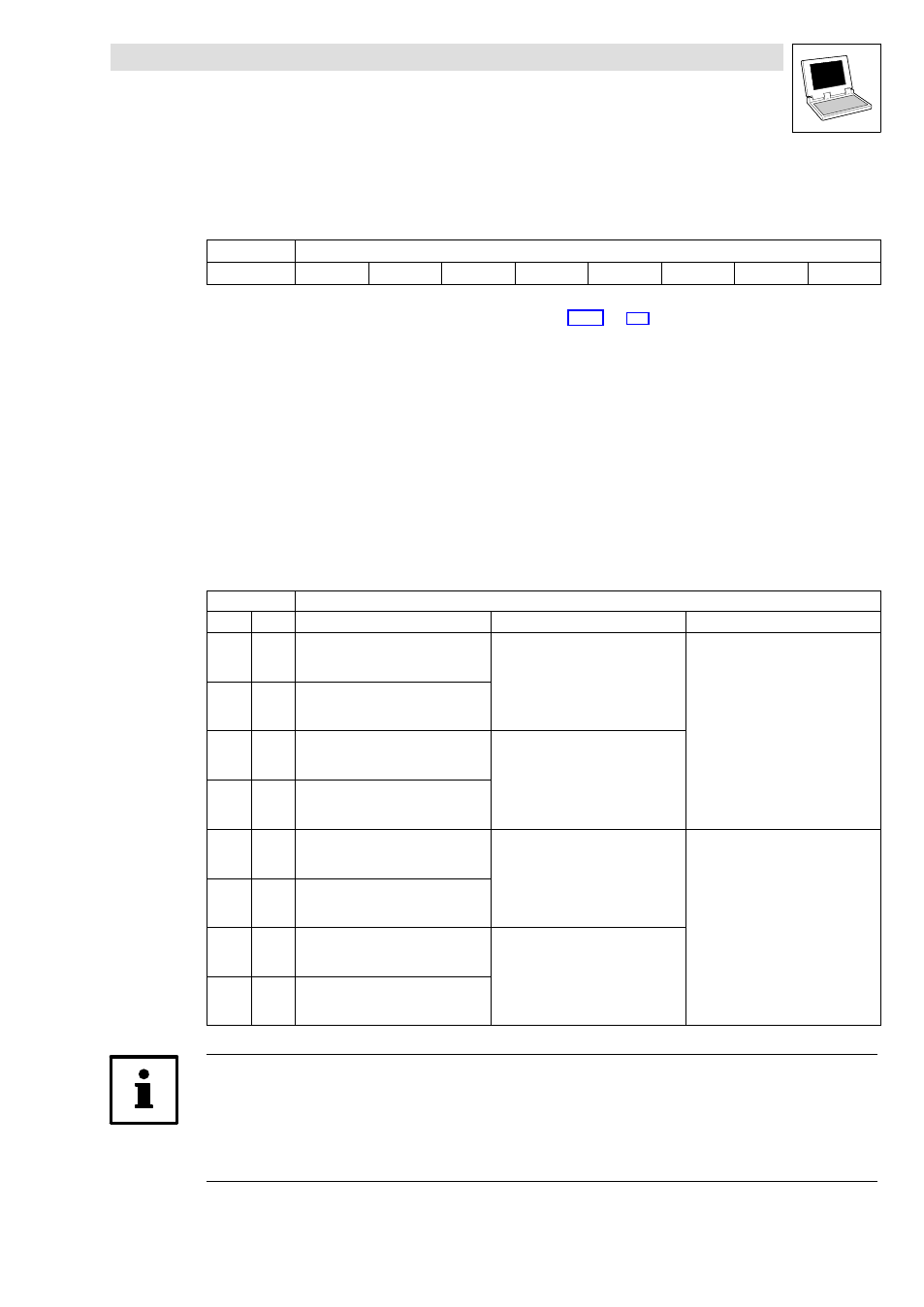
Process data telegram
The process data telegram consists of an identifier and 8 bytes of user data.
11bit
8 bytes user data
Identifier
Byte 1
Byte 2
Byte 3
Byte 4
Byte 5
Byte 6
Byte 7
Byte 8
Information on the identifier can be found in chapter 2.4.1.
(
8.1.4
Assignment of the user data to variables
Several variables of different data types are assigned to the user data to be transmitted and received.
Thus, the data in the PLC program can be optionally interpreted as:
·
binary information (1 bit)
·
status word/quasi−analog value (16 bit)
·
angle information (32 bit)
Variables for user data to be transmitted
User data
Assigned variables
Byte
Bit
Variable (1 bit)
Variable (16 bit)
Variable (32 bit)
1
0
...
7
FIF_CAN1_bFDO0_b
...
FIF_CAN1_bFDO7_b
FIF_CAN1_nOutW0_a
2
0
...
7
FIF_CAN1_bFDO8_b
...
FIF_CAN1_bFDO15_b
3
0
...
7
FIF_CAN1_bFDO16_b
...
FIF_CAN1_bFDO23_b
FIF_CAN1_nOutW1_a
4
0
...
7
FIF_CAN1_bFDO24_b
...
FIF_CAN1_bFDO31_b
5
0
...
7
FIF_CAN1_bFDO32_b
...
FIF_CAN1_bFDO39_b
FIF_CAN1_nOutW2_a
FIF_CAN1_dnOutD1_p
6
0
...
7
FIF_CAN1_bFDO40_b
...
FIF_CAN1_bFDO47_b
7
0
...
7
FIF_CAN1_bFDO48_b
...
FIF_CAN1_bFDO55_b
FIF_CAN1_nOutW3_a
8
0
...
7
FIF_CAN1_bFDO56_b
...
FIF_CAN1_bFDO63_b
Note!
Avoid simultaneous overwriting via different variable types to ensure data consistency.
For instance, if you want to write the bytes 5 and 6, only use the variable FIF_CAN1_dnOutD1_p,
FIF_CAN1_nOutW2_a, or only the variables FIF_CAN1_bFDO32_b ... FIF_CAN1_bFDO47_b for this
purpose!