4 can2_io (node number: 32), Can2_io (node number: 32), Pter 7.4 – Lenze DDS System bus CAN for PLC User Manual
Page 102: System bus (can) for lenze plc devices, Can system blocks, A sync telegram is not required
7.4
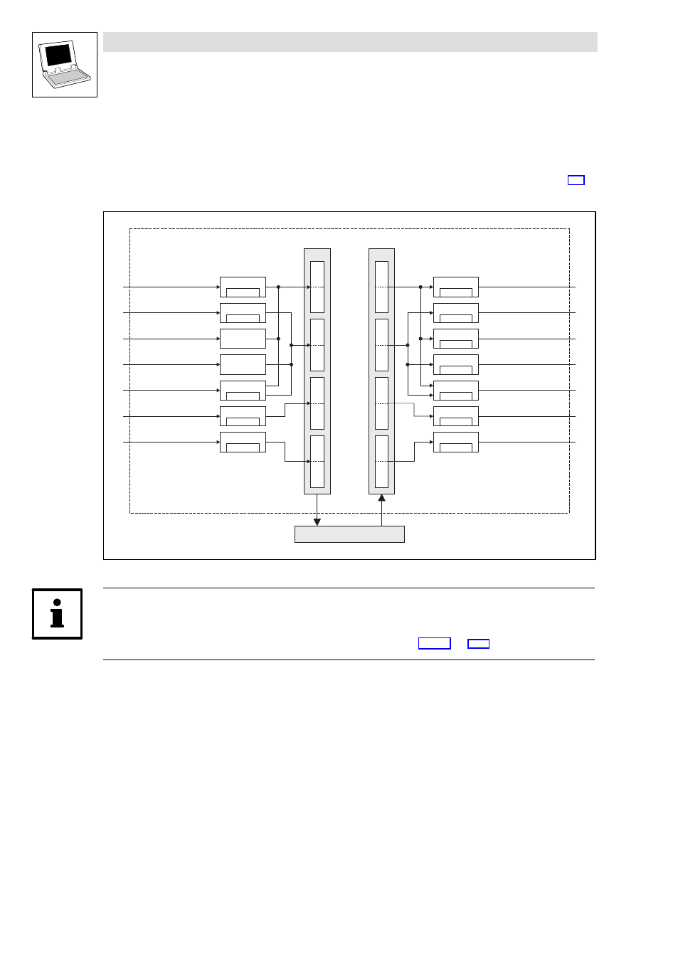
CAN2_IO (node number: 32)
System bus (CAN) for Lenze PLC devices
CAN system blocks
7−14
L
PLC−Systembus EN 2.0
7.4
CAN2_IO (node number: 32)
This SB serves to transmit event−controlled or time−controlled process data via the system bus.
·
The setting of the transmission mode (event− or time−controlled) is effected via C0356.
(
·
A sync telegram is not required.
CAN2_nInW1_a
CAN2_nInW2_a
CAN2_bInB
_b
0...15
CAN2_bInB
_b
16...31
System bus interface
Byte
7
8
5
6
3
4
1
2
Byte
7
8
5
6
3
4
1
2
CAN2_nOutW1_a
CAN2_nOutW2_a
CAN2_nOutW3_a
CAN2_bFDO
_b
16...31
CAN2_dnOutD1_p
CAN2_IO
DINT
WORD
WORD
WORD
16 x BOOL
DINT
Output user data
(8 bytes)
Input user data
(8 bytes)
L
H
L
H
CAN2_bFDO
_b
0...15
16 x BOOL
CAN2_nOutW4_a
WORD
WORD
WORD
16 x BOOL
16 x BOOL
CAN2_nInW3_a
CAN2_nInW4_a
WORD
WORD
CAN2_dnInD1_p
C0868/4
C0868/5
C0869/2
C0868/6
C0868/7
C0866/4
C0866/5
C0863/3
C0863/4
C0867/2
C0866/6
C0866/7
Fig. 7−4
CAN2_IOsystem block
Tip!
Via C0357/2 you can set the monitoring time for the data reception. (Lenze setting: 3000 ms)
·
Further information on this subject can be found in chapter 3.12.1.
(
^ 3−11)