System bus (can) for lenze plc devices, General information – Lenze DDS System bus CAN for PLC User Manual
Page 16
System bus (CAN) for Lenze PLC devices
General information
2−4
l
PLC−Systembus EN 2.0
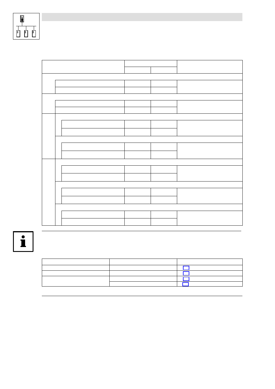
The following table contains the preset basic identifiers of the Lenze devices:
Identifier =
basic identifier
+ node address of the node
dec
hex
·Network management
Tx (transmission)
0
0
Rx (reception)
0
0
Sync telegram
Tx (transmission)
128
80
Rx (reception)
128
80
SDOs
Parameter data channel 1
Output (transmission)
1536
600
+ C0350
+ C2350
+ C2450
(CAN)
(XCAN)
(FIF−CAN/CAN−AUX)
Input (reception)
1408
580
Parameter data channel 2
Output (transmission)
1600
640
+ C0350
+ C2350
+ C2450
(CAN)
(XCAN)
(FIF−CAN/CAN−AUX)
Input (reception)
1472
5C0
PDOs
CAN1_IO (cyclic process data)
CAN1_IN
512
200
+ C0350
+ C2350
+ C2450
(CAN)
(XCAN)
(FIF−CAN/CAN−AUX)
CAN1_OUT
384
180
CAN2_IO (event− or time−controlled process data)
CAN2_IN
640
280
+ C0350
+ C2350
+ C2450
(CAN)
(XCAN)
(FIF−CAN/CAN−AUX)
CAN2_OUT
641
281
CAN3_IO (event− or time−controlled process data)
CAN3_IN
768
300
+ C0350
+ C2350
+ C2450
(CAN)
(XCAN)
(FIF−CAN/CAN−AUX)
CAN3_OUT
769
301
Tip!
For the process data objects you can also set an individual identifier via the following codes, which
is independent of the node address:
Code
Interface
Information
C0353 / C0354
CAN (system bus interface)
^ 3−4
C2353 / C2354
XCAN (AIF interface)
^ 4−4
C2453 / C2454
FIF−CAN (FIF interface)
^ 5−4
CAN−AUX (system bus interface)
^ 6−4