2 structure of the description, Structure of the description, System bus (can) for lenze plc devices – Lenze DDS System bus CAN for PLC User Manual
Page 11: Preface and general information, Information on return values for a function
System bus (CAN) for Lenze PLC devices
Preface and general information
1.1
About this Manual
1−3
L
PLC−Systembus EN 2.0
1.1.2
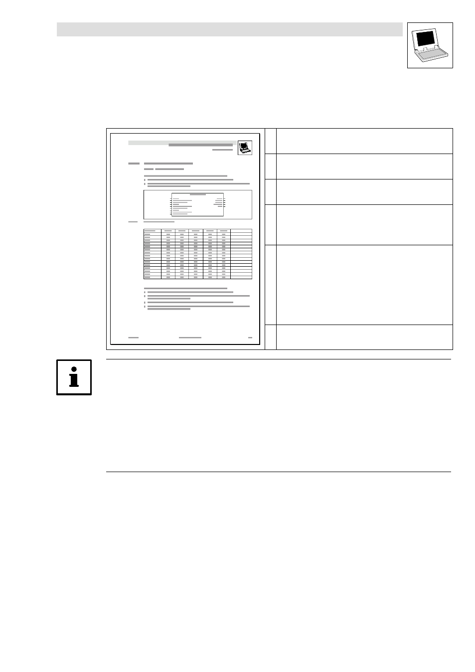
Structure of the description
The descriptions of the individual functions/function blocks as well as of system blocks contained
in this Manual have the same structure:
Headline with SB identifier
SB function and node number
Short description of the SB and its most important features
System block chart including all corresponding variables
·
Input variables
·
Output variables
Table giving information about input and output variables:
·
Identifier
·
Data type
·
Signal type
·
Address
·
Display code
·
Display format
·
Information
Detailed functional description of the SB
Information on return values for a function
If it was not possible to carry out a function faultlessly, a negative return value is sent back,
representing an error number.
·
Each error number is assigned to a corresponding error cause in the Meaning column.
·
If different error numbers (−1, −2, ...) may apply, a specific digit (1, 2, ...) in the Priority column
additionally is assigned to the error number.
– The smaller this digit, the higher is the priority of the associated error number.
– If several error causes are available at the same time when a function is carried out, always
the error number with the highest priority is returned by the function.