Appendix a, Linkpower supply kit, Installation procedure – ETC SmartPack CE Wall Mount User Manual
Page 21: Appendix a linkpower supply kit
A
LinkPower Supply Kit
19
Appendix A
LinkPower Supply Kit
One SmartLink LinkPower Supply (S-LPS) powers up to four wall stations over the
SmartLink™ network.
Installation Procedure
The LinkPower supply kit includes a LinkPower supply and four screws.
Step 1:
Remove power from the control electronics by turning the Standby breaker off.
Step 2:
Remove the two screws securing the I/O panel to the chassis.
Step 3:
Fold the I/O panel down to reveal the control terminations.
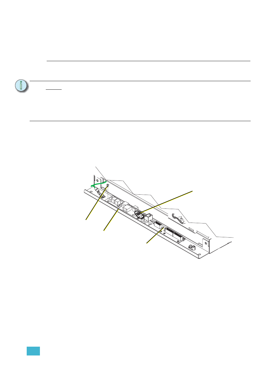
Step 4:
Angle the LinkPower supply board approximately 10° and insert the four pins as
found on the LinkPower supply into the receptacle on the I/O board.
Step 5:
Align the LinkPower supply with the four screw mounts located on the I/O panel
and secure with the four screws provided. Do not over tighten the screws.
Step 6:
Close the I/O panel and secure with the two screws.
Step 7:
Re-apply power to the control electronics.
N o t e :
You may have only one station power source on the SmartLink network. This
source may be either the LinkPower Supply (S-LPS) or a SmartLink Station Power
Module (S-SPM) which powers up to 16 SmartLink stations. As well, you may
have up to four SmartLink host products in a SmartLink system. One SmartLink
host product (SmartPack, SmartSwitch, Unison DRd with SmartLink or Sensor +
with SmartLink) in the system must have a LinkPower Supply or Station Power
Module installed for wall station power.
Step 4
Step 5
LinkPower
supply
I/O board