Set a level for a dimmer, Verify dmx512 operation, Troubleshooting smartlink – ETC SmartPack CE Wall Mount User Manual
Page 19: Verify dmx512 operation troubleshooting smartlink
Installation Procedure
17
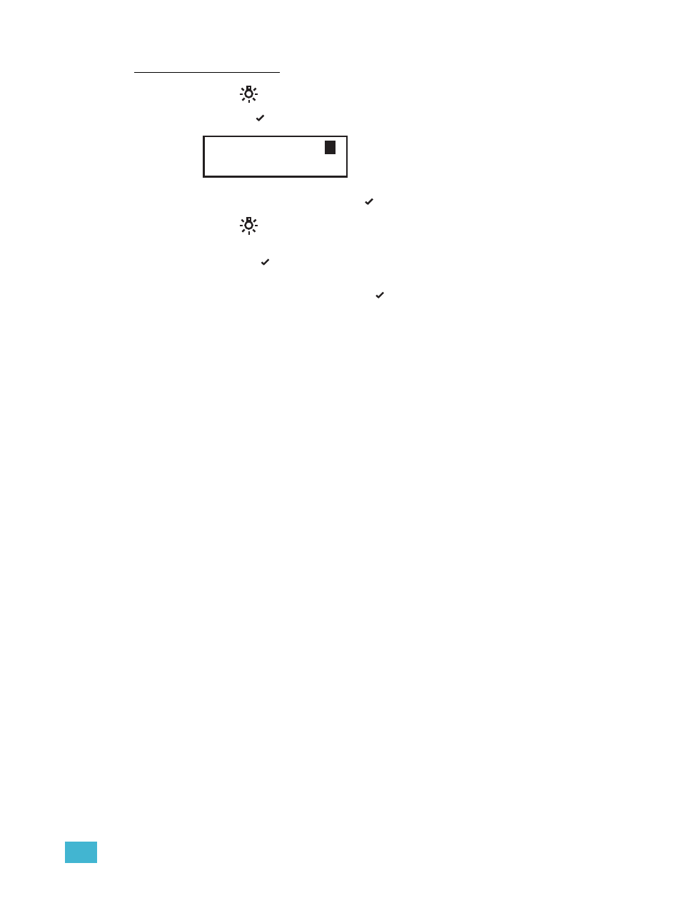
Set a level for a dimmer:
Step 1:
Press
to enter the Test menu.
Step 2:
Use < or
to scroll the selection of dimmers, choose one or [ALL] dimmers.
Step 3:
Use + or - to set a level, press
. The menu will progress to the next dimmer.
Step 4:
Press
. “Exit Test Mode” displays.
•
Exit Test Mode and retain all Test levels, scroll to [Keep Test On] and
press
.
•
Exit Test menu, clearing all Test levels and return to the previous menu,
scroll to [Test: all off], press
.
•
Press < to return to the Test menu.
•
Press << to exit the Test menu, clearing all Test levels, and return to the main
menu.
Verify DMX512 Operation
Test each load with DMX512 input using a controle console or DMX512 test device.
Troubleshooting SmartLink
After all SmartLink control stations are installed and connected to the SmartLink enabled
product, check for shorts and cross-connections with a digital voltmeter.
•
Check the voltage between Net A and ground. This reading should be between 18
- 21 Volts.
•
Check the voltage between Net B and ground. This reading also should be
between 18-21 Volts.
•
Check the voltage between Net A and Net B. This reading should be between 36-
42 Volts.
Check that two LED indicators (located at CR1 and CR2) are illuminated on the LinkPower
supply board.
•
If both are illuminated the data connections are good.
•
If CR1 is illuminated but not CR2, Net A is shorted to ground.
•
If CR2 is illuminated but not CR1, Net B is shorted to ground.
•
If neither LED is illuminated, Net A and Net B are both shorted.
If you have any difficulties installing your system, please contact ETC Technical Services
at the office nearest you.
Test Dimmer: [ All ]
T
Level: 100%