Installation procedure, Install mounting hardware, Mount the smartpack – ETC SmartPack CE Wall Mount User Manual
Page 10: Install mounting hardware mount the smartpack
8
SmartPack Wall Mount Installation Manual
Installation Procedure
Install Mounting Hardware
Step 1:
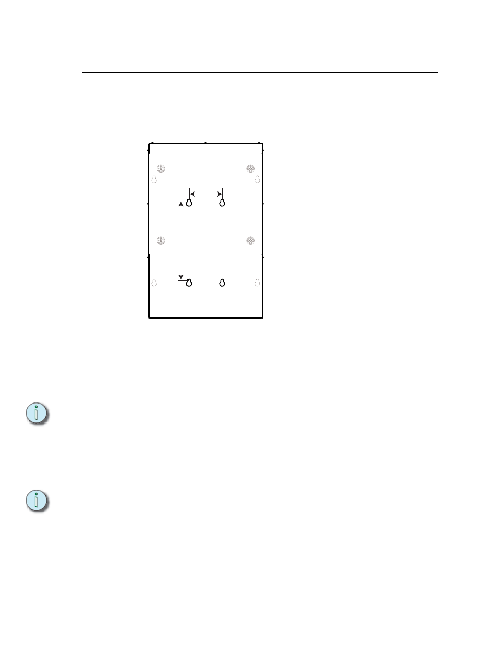
Affix the mounting template, if included in the shipping carton, to the wall to guide
the placement of the mounting bolts or screws. If the mounting template is not
provided, use the measurements below.
Step 2:
Install the hardware required for mounting the SmartPack using the four
measured keyholes on the mounting template as a guide.
•
Four 6-8mm (1/4” - 3/8”) bolts or screws, 50-100mm (2 - 4”) long, and
suitable wall plugs are suggested mounting hardware.
•
Both the surface and the mounting hardware must support 23kg (50lbs).
•
Expose at least 25mm (1”) of threads for mounting the SmartPack.
Mount the SmartPack
Step 1:
Remove the four screws securing the cover to the SmartPack.
Step 2:
Remove the cover assembly.
Step 3:
Mount the SmartPack to the mounting bolts previously installed.
Step 4:
Tighten the bolts securely.
•
Check for a plumb installation and follow all local code restrictions.
N o t e :
Access holes to tighten bolts / screws are shown in the
graphic on
N o t e :
The SmartPack Wall Mount unit ships with a debris shield to protect the
electronics during installation. Leave this shield in place during installation and
remove only after installation is complete and before energization.
127mm
(5.0”)
305mm
(12.0”)
• SmartPack Wall Mount units may be
mounted up to two high by any width.
Allow clearances as described on
• Overall dimensions of the enclosure:
435mm x 157mm x 666mm
(17.2” x 6.2” x 26.2”)
or, for ThruPower or Relay racks:
435mm x 157mm x 741mm
(17.2” x 6.2” x 29.2”)