Connect control wiring, Emergency/smartlink – ETC SmartPack CE Wall Mount User Manual
Page 14
12
SmartPack Wall Mount Installation Manual
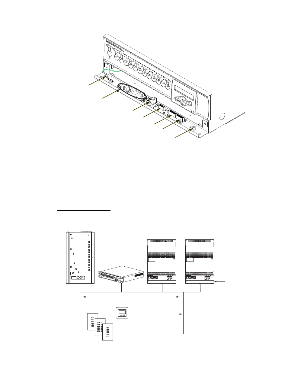
Connect Control Wiring
Emergency, SmartLink, DMX In and DMX Pass-Thru are connected in the
I/O compartment of the SmartPack Wall Mount unit. Each connection uses a pluggable
screw terminal which can be removed for easy wiring.
The RJ45 connection labeled J2 on the I/O board connects the I/O control board to the
control CPU board for data communication to the SmartPack. This connection is made at
the factory prior to shipment.
The LinkPower supply provides power for up to four SmartLink wall stations per system.
SmartPack Wall Mount is available with or without the LinkPower supply option. For field
installation of the LinkPower supply reference
Emergency/SmartLink
SmartLink is a control protocol that provides added functionality to the SmartPack dimming
pack for inter-connectivity and shared communication of specific data to other SmartLink
enabled host products. Reference the SmartPack User Manual for configuration details.
I/O panel to
chassis ground
Link Power supply
(optional)
Data to CPU
Emergency /SmartLink
DMX In
DMX Thru
ESD Ground
Preset 5
Preset 1
Preset 2
Preset 4
Preset 3
Preset 10
Preset 6
Preset 7
Preset 9
Preset 8
Preset 5
Preset 1
Preset 2
Preset 4
Preset 3
Preset 5
Preset 1
Preset 2
Preset 4
Preset 3
Back
Up
Enter
Recall
Preset
Hold
Down
Presets, Sequence,
Sequence Timing
SmartPack
SmartPack
Unison DRd12
rack
LinkPower
supply
installed
Belden 8471 plus
12.5mm
2
ESD
drain
SmartLink
Stations
SmartPack
SmartLink
ATC