Series connected eritech – ERICO 3000 ERITECH SYSTEM User Manual
Page 54
INSTALLATION, OPERATION AND MAINTENANCE MANUAL
52
www.erico.com
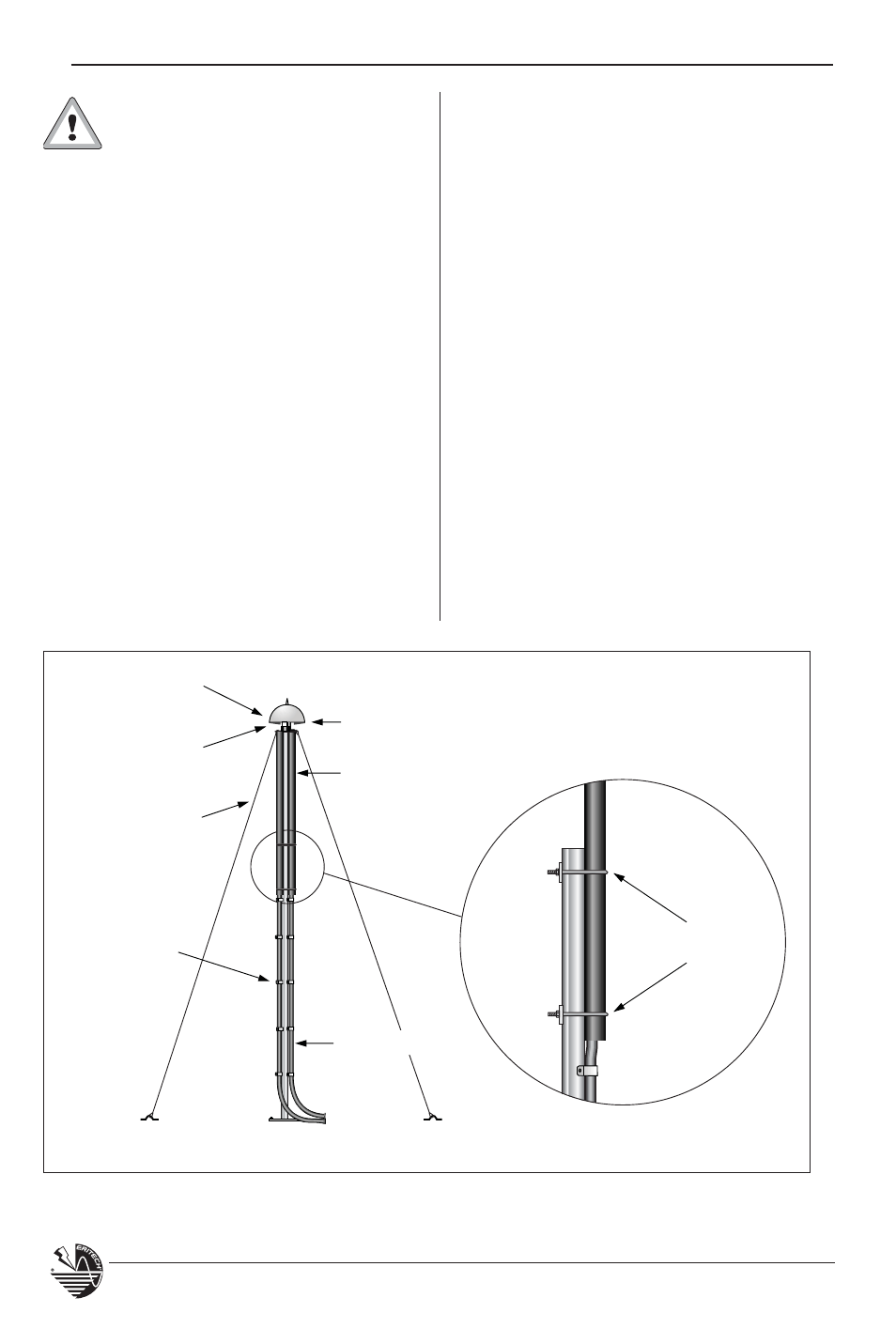
2 x FRP Mast
(2 m or 4.6 m)
ERITECH
®
DYNASPHERE
Guy Kit
Aluminum Mast
U Bolts
2 x ERITECH
®
ERICORE
Cable
Guy Ring
1 x TERMDUALCOUP
The twin ERITECH
®
ERICORE conductors
are run in a parallel manner down to
ground (see Figure 36). The usual
conductive saddle spacing applies.
At the point of connection to the
grounding system, each ERITECH
®
ERICORE cable is fitted with an ERITECH
ERICORE lower termination kit, and
attached to the grounding system
Series connected ERITECH
®
ERICORE cable sections
As an alternative to running twin
ERITECH ERICORE conductors, a single
ERITECH ERICORE cable can be run, but
it is broken into several sections, none
of which exceeds the cable breakdown
voltage. This is done by periodically
connecting the cable to a conductive
structural point (see Figure 37).
IMPORTANT – To maintain the
necessary clearance between
the ERITECH
®
DYNASPHERE air
terminal and the top of the mast, the
FRP mast must protrude at least
1400 mm above the top of the
aluminum mast. The following shows
the required positioning dimensions for
the two available FRP mast sizes.
2 meter FRP Mast
Overlap on aluminum mast = 600 mm
Protrusion above aluminum mast = 1400 mm
4.6 meter FRP Mast
Overlap on aluminum mast = 1.5 m
Protrusion above aluminum mast = 3.1 m
The standard guy ring part may be fitted to
the Dual Coupling Termination and used
with the usual guying kit.
Figure 35: Typical mast arrangement using the twin ERITECH
®
ERICORE arrangement.