ERICO 3000 ERITECH SYSTEM User Manual
Page 33
INSTALLATION, OPERATION AND MAINTENANCE MANUAL
31
www.erico.com
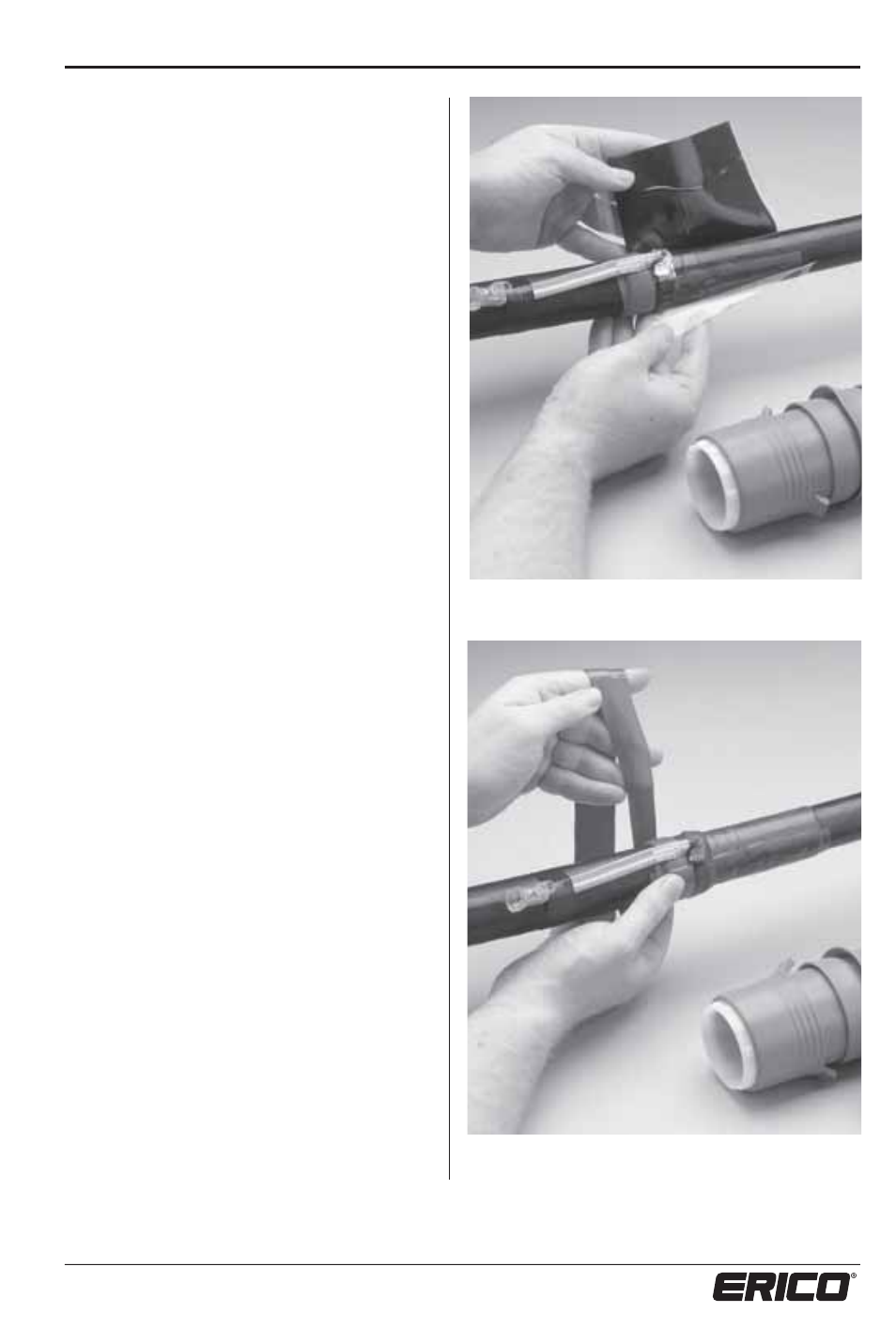
11. Remove one release foil from the
stress control patch (green) and apply it
level with the outer insulation cut, against
the red sealant tape, (see photo 7). Wrap
the entire patch around the cable as
shown and remove the release foil during
installation. Avoid air pockets, wrinkles or
creases.
12. Wrap one layer of sealant tape (red)
with a small overlap and slight tension
over the braid wire and previously applied
sealant tape, below and level with the
(green) stress control patch, (see photo 8).
13. Take apart the ERITECH
®
ERICORE
coupling, ensuring there are 4 pieces.
There should be:
t"$PNQSFTTJPO/VU
t"$PNQSFTTJPO3JOH
t"$PNQSFTTJPO$POF
t".BJO$PVQMJOH1JFDF
14. Place the compression nut and
compression ring of the coupling set over
the strands and copper tape layer. Check
the order and orientation of the nut and
ring against Figure 22 on page 36.
15. Unwrap the material double tape layer
back to the compression ring. Place the
compression cone between the filler core
and the copper strands as shown in Figure
22. The cone should be “pushed on” until
it is flush with the end of the filler core.
Neatly form the copper strands back over
the cone in their original order.
Photo 7: Applying the stress control patch. In line with
initial outer layer cut and over the bonding braid.
Photo 8: Apply the sealant tape below the stress
control patch.