Penetrations, Routing – ERICO 3000 ERITECH SYSTEM User Manual
Page 18
INSTALLATION, OPERATION AND MAINTENANCE MANUAL
16
www.erico.com
Penetrations
Before routing the downconductor through
any penetrations, ensure that:
t
If un-terminated, a minimum hole
diameter of 50 mm (2 in.) is provided.
t
If terminated, a minimum hole diameter
of 60 mm (2
3
⁄
8
in.) is provided.
t
Enough physical protection (conduit
or similar) is provided to stop the
downconductor from being damaged
when being fed through the penetration.
t
When feeding the upper termination
of the downconductor through any
penetrations, the termination sheds
(flanges) should be temporarily wrapped
in insulation tape to reduce their
diameter and protect them against
abrasion. This is very important as the
cold-shrink tubes are susceptible to
tearing if nicked or scuffed.
If either side of the penetration requires
environmental protection ie: waterproofing,
air-con pressure seal, etc., use a suitable
sealant or deck sealing gland.
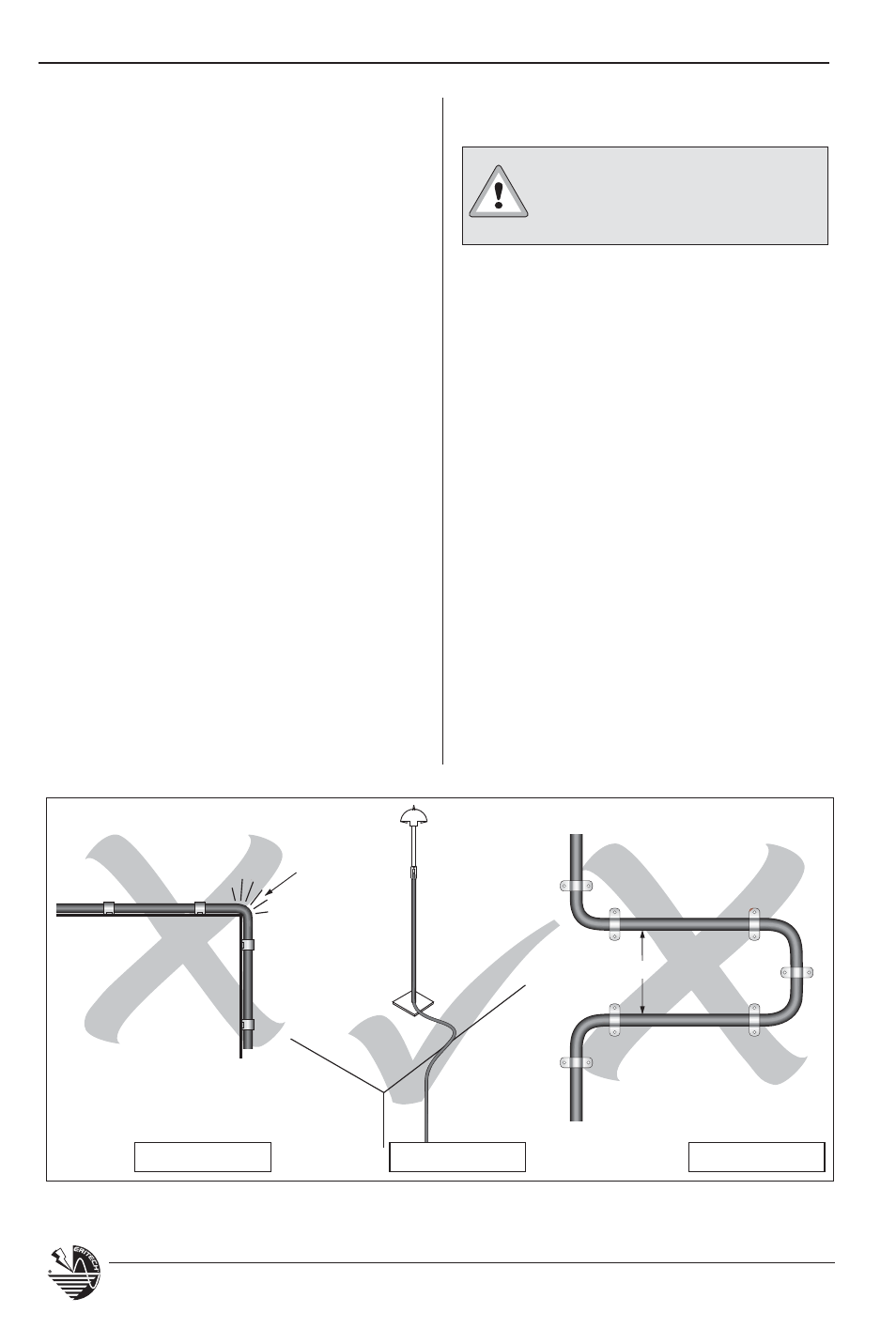
The route taken by the down-
conductor is very important
and must follow these rules:
Routing
t
Carefully survey the intended route
of the downconductor immediately
prior to the installation to check for
any alterations that may effect the
original design, ie: structural changes,
new antenna or mast installations, air
conditioning towers or ducting, etc.
t
Use the most direct route practical to
minimize the downconductor length.
t
To minimize the risk of side-flash,
DO NOT route the downconductor back
beside itself after change of direction,
ie: 180º.
t
Minimize number of bends.
t
Minimize strain on the downconductor
during installation.
< 2000 mm (80 in.)
Radius
< 500 mm
(20 in.)
Figure 8: Correct & incorrect cable routing methods.
INCORRECT
CORRECT
INCORRECT