Installation instruc tions – Poison Spyder JK FRONT CRUSHER FLARES User Manual
Page 2
INSTALLATION
INSTRUC
TIONS
Poison Spyder Customs • JK FRONT CRUSHER FLARES INSTALL
Page 2
©2010 POISON SPYDER CUSTOMS, INC. • 951-849-5911 • WWW.POISONSPYDER.COM
IMPORTANT: Poison Spyder Customs, Inc. is
NOT RESPONSIBLE for paint or powder coating
costs, damage to paint or powder coating, or
costs associated with inadvertently painting or
powder coating components that are defective
or were shipped or assembled in error. It is the
customer’s responsibility to pre-install and verify
that all parts are correct prior to paint or powder
coat.
NOTE ON STEEL CRUSHER FLARES: The
small space where the top plate meets the outer
tube is not continuously welded, and therefore
not completely sealed against moisture. Please
make sure that paint or powder coat are applied
heavily in this area, to seal the seam up against
water intrusion and rust forming (this is not
an issue on aluminum Crusher Flares). Thick
coatings such as spray-on bedliner material will
also seal it up if applied correctly. If your paint or
coating is very thin or not thoroughly applied to
this area, apply a bead of silicone sealant to the
seam on the underside of the top plate where it
meets the tubing.
INSTALLATION PROCEDURE
The following procedure is for preparation and
installation of the JK Crusher Flare on one side of
the Jeep. Once complete, repeat the procedure
for the other side.
1. Park vehicle on a level surface and set the
emergency brake. You will want to wear eye
protection beyond this point in time.
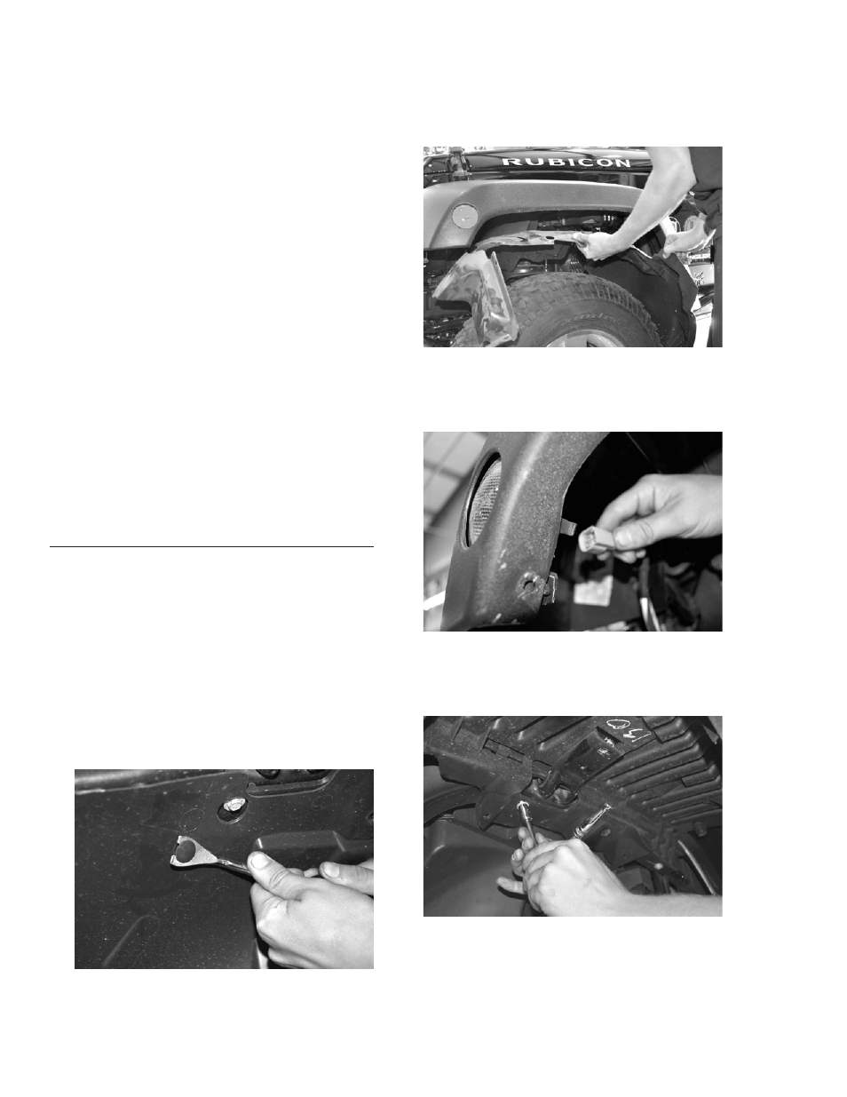
2. Remove the inner fender by using a 10mm
socket to remove the factory hex head bolts,
and a push-in retainer removal tool to pop
out the plastic push-in retainers.
FIGURE 2
Try not to damage the inner fender or the
plastic retainers. Set the inner fender, all
of the plastic retainers and hex head bolts
aside, as some will be re-used during the
installation process.
FIGURE 3
3. Disconnect the side marker lamp by pulling
the wiring harness plug out of the lamp
socket.
FIGURE 4
4. Remove the plastic fender/flare support.
You may need to remove more hex head
bolts and/or plastic retainer clips.
FIGURE 5
Set the fender/flare support aside. It will not
be re-used.