Figure 3-35: distribution box connections, Distribution box ground / primary power – Hale FoamLogix 6.5 User Manual
Page 90
❑ Electrical Installation
90
FoamLogix 3.3 / 5.0 / 6.5 Installer / Operations Manual
p/n: 029-0021-68-0
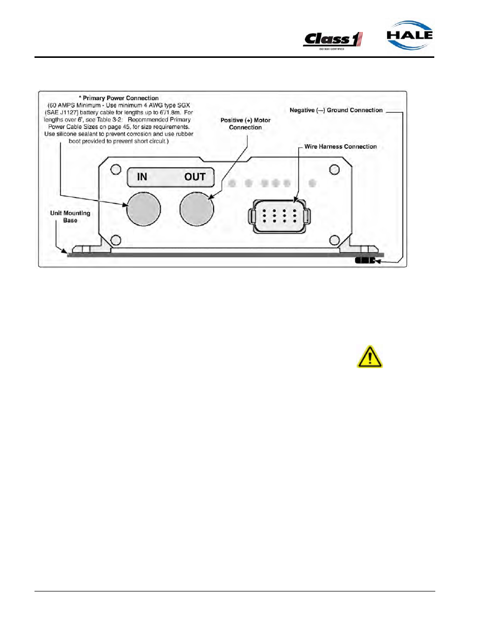
Figure 3-35: Distribution Box Connections
Distribution Box Ground / Primary Power
CAUTION !
CONNECT THE PRIMARY POSITIVE LEAD FROM THE TERMINAL BLOCK TO
THE MASTER SWITCH TERMINAL OR RELAY TERMINAL USING MINIMUM 4
AWG TYPE SGX (SAE J1127), CHEMICAL RESISTANT, BATTERY CABLE
AND PROTECT WITH WIRE LOOM.
PREVENT CORROSION OF POWER AND GROUND CONNECTIONS BY SEAL-
ING THESE CONNECTIONS WITH THE SILICONE SEALANT PROVIDED.
Ground Connection
Be sure the Hale FoamLogix system is grounded to the chassis. Use a
short length of wide flat ground strap, at least 1-1/4” (32mm) wide and less
than 18” (457 mm) long, to reduce the potential of RFI emitted by this
connection.
A stud is located on the mounting base, labeled NEG (-), to attach the chas-
sis ground strap to the Hale FoamLogix system. (See Figure 3-35: “Distri-
bution Box Connections” on page 90.)