Flow sensor calibration, Figure 4-5: flow sensor calibration - display – Hale FoamLogix 6.5 User Manual
Page 114
❑ Setup and Calibration
114
FoamLogix 3.3 / 5.0 / 6.5 Installer / Operations Manual
p/n: 029-0021-68-0
3. The display shows CAL for several seconds, followed by CO (or LO when
display is set to metric). (See Figure 4-4: “Password and Calibration Modes
- Display” on page 113.)
4. The FLOW LED (Water Flow Sensor Calibration) also illuminates.
Flow Sensor Calibration
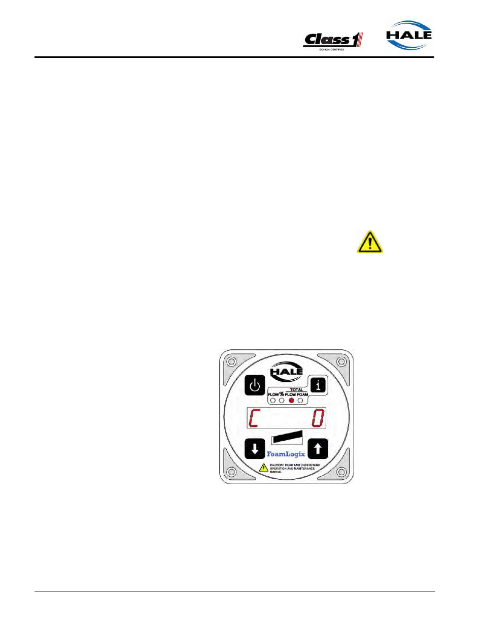
Verify flow sensor calibration during NFPA/UL testing of the apparatus and
delivery to end user. (See Figure 4-5: “Flow Sensor Calibration - Display.”)
IMPORTANT !
AN ACCURATE FLOW MEASURING DEVICE MUST BE USED TO MEASURE
THE WATER FLOW WHEN CALIBRATING THE FLOW SENSOR. USE A SUIT-
ABLE SIZE, SMOOTH BORE, NOZZLE AND AN ACCURATE AND CALIBRATED
PITOT GAUGE INSTRUMENT. HAND HELD PITOT GAUGES ARE USUALLY
NOT VERY ACCURATE.
MAKE SURE THE SYSTEM IS CALIBRATED WITH AN ACCURATE FLOW MEA-
SURING DEVICE.
1. Determine the water flow normally
expected from the discharge outlet and
establish flow.
2. Make sure the water flow established is
within the range of the flow sensor mon-
itoring the discharge.
For example, establish a flow rate of 150
GPM (568 LPM) of water through a noz-
zle and Pitot system. Compare the cal-
culated flow value to the value shown on
the control unit display.
3. Press the or button and set the
reading to match the actual flow calcu-
lated from the Pitot gauge reading.
4. Decrease fire pump pressure by approximately one half (1/2) and recalculate
water flow rate.
Figure 4-5: Flow Sensor Calibration -
Display