Figure 3-12: flow sensor placement, Saddle clamp installation – Hale FoamLogix 6.5 User Manual
Page 64
❑ Installer Installation
64
FoamLogix 3.3 / 5.0 / 6.5 Installer / Operations Manual
p/n: 029-0021-68-0
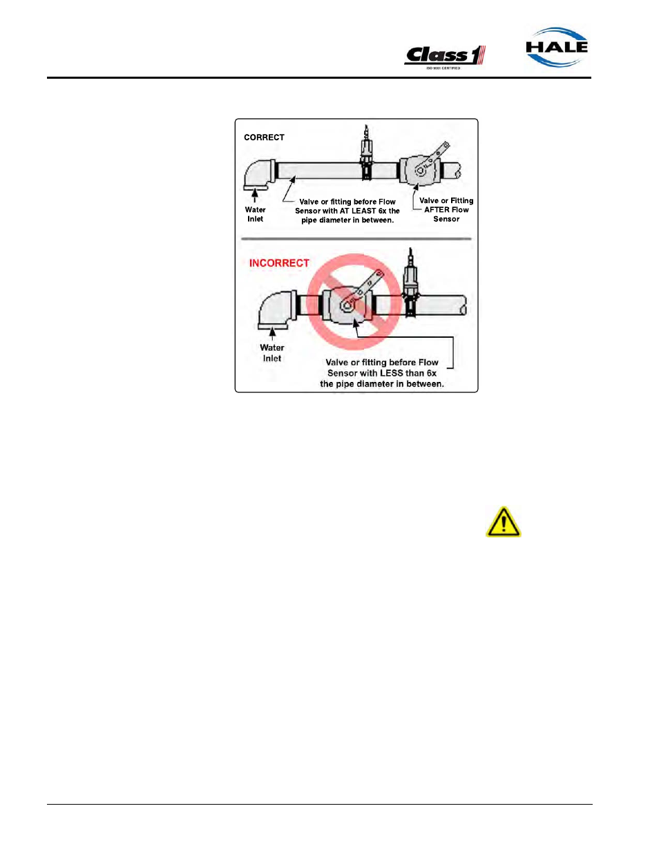
The downstream piping
length is not as critical,
but there must be a short
length of straight pipe
with no fittings or valves
immediately after the flow
sensor paddle wheel.
Two to three times the
pipe diameter is recom-
mended.
Do not mount a flow sen-
sor directly after an
elbow or valve. Valves
create severe turbulence
when they are “gated.”
Saddle Clamp Installation
(See Figure 3-13: “Flow Sensor/Saddle Clamp Installation,” on page 65.)
IMPORTANT !
THE PADDLE WHEEL SHOULD BE INSTALLED AS CLOSE TO UPRIGHT AS
POSSIBLE WITHIN THE RANGE SHOWN FIGURE 3-9: “FLOW SENSOR TEE
POSITION RANGE” ON PAGE 62. FOR PROPER OPERATION DO NOT LET
THE FLOW SENSOR ROTATE MORE THAN 85° IN EITHER DIRECTION.
Installation of the Paddle Wheel Flow Sensor using a saddle clamp requires
a 1.385”/1.390” (35/35.3mm) bored hole in the pipe. A minimum of six (6)
times the pipe diameter of straight run pipe without any fittings is necessary
prior to the position of this hole.
The flow sensor requires a spacer and eight stainless steel internal hex
head screws. These are supplied with the sensor.
Four 6-32 x 1/2” screws attach the spacer to the saddle clamp mount, and
four 6-32 x 3/4” screws with lock washers attach the paddle wheel to the
spacer.
Figure 3-12: Flow Sensor Placement