9 system configuration, Figure 2-4: foamlogix available models – Hale FoamLogix 6.5 User Manual
Page 27
27
FoamLogix 3.3 / 5.0 / 6.5 Installer / Operations Manual
p/n: 029-0021-68-0
Intr oduction
❑
2.9
SYSTEM CONFIGURATION
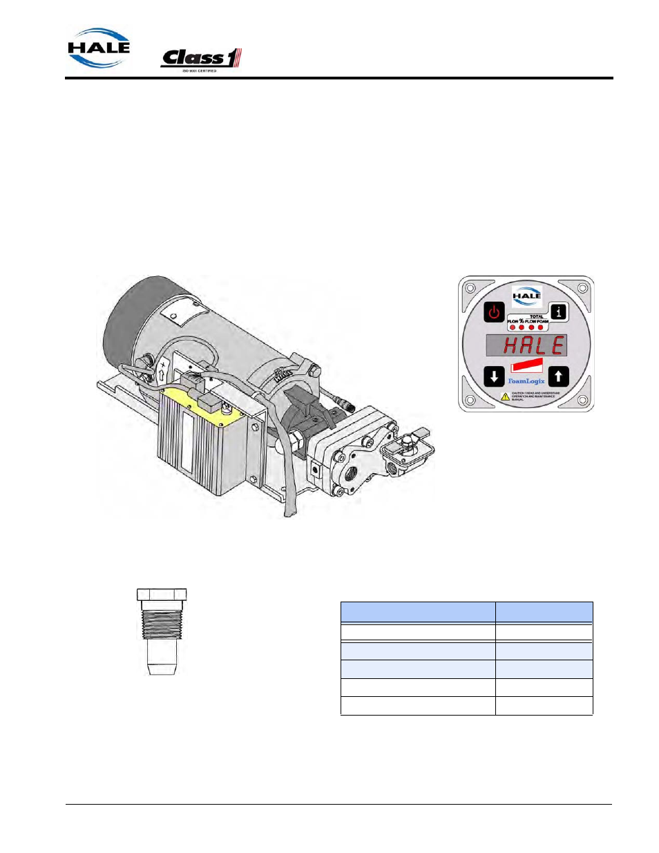
Hale Foam Proportioner System, Models 3.3, 5.0 or 6.5
All Hale Foam systems include a: Foam Pump/Motor Assembly, Control
Unit, Main Harness and Check Valve/Injector Fitting. Also see Section 8
“Illustrated Parts Breakdown” on page 157.
Figure 2-5: Hale Foam Proportioner Systems, Models 3.3, 5.0 and 6.5
FoamLogix Model
Part Number
Model 6.5, with 24VDC Motor
501-4480-04-0
Model 5.0, with 12VDC Motor
501-3130-04-0
Model 5.0 with 24VDC Motor
501-3130-03-0
Model 3.3 with 12VDC Motor
501-3120-03-0
Model 3.3 with 24VDC Motor
501-3120-04-0
Figure 2-4: FoamLogix Available Models
Control Unit
p/n: 111530
Check Valve/Injector Fitting
p/n: 038-1790-00-0
Foam Pump/Motor Assembly
(Shown with Bypass Valve when configured
for MDT II, MST or No Tank Selector Option)