Table 3-3: recommended foam tank capacity, Foam pump mounting, Figure 3-4: foamlogix pump installation – Hale FoamLogix 6.5 User Manual
Page 57
57
FoamLogix 3.3 / 5.0 / 6.5 Installer / Operations Manual
p/n: 029-0021-68-0
Ins ta lle r Ins ta lla tion
❑
❑
Baffling
❑
Drain facilities
Foam tank capacities for the Hale
FoamLogix 3.0, 5.0 or 6.5 are based
on NFPA requirements for flamma-
ble liquid (Class “B”) fire suppres-
sion. (See Table 3-3: “Recommended
Foam Tank Capacity.”)
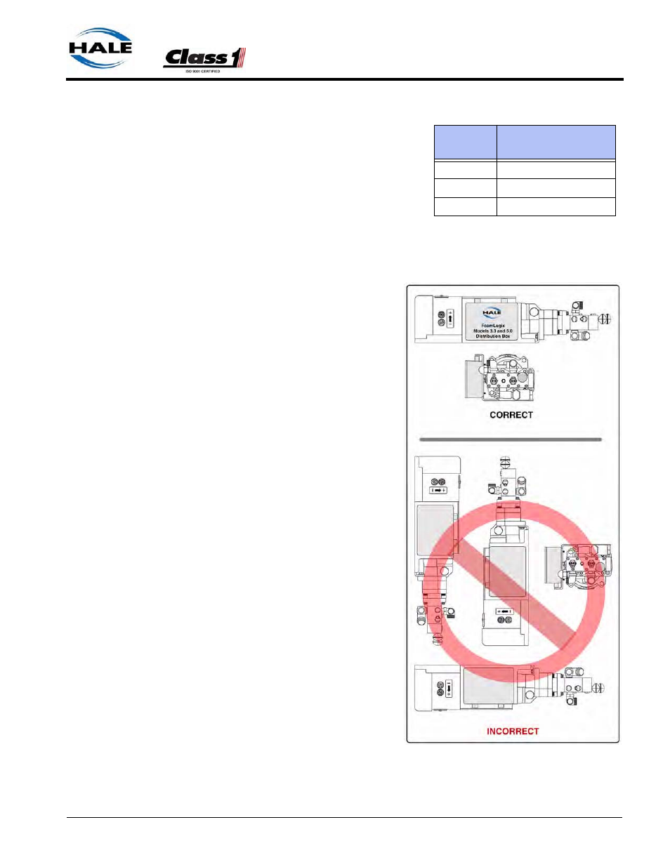
Foam Pump Mounting
Position the foam pump and
motor assembly in the desired
location on the apparatus. When
installing the foam pump and
motor assembly, the assembly
must be kept in a HORIZONTAL
position with the base plate on
the bottom. (See Figure 3-4:
“FoamLogix Pump Installation.”)
Although the system is sealed
and designed to be resistant to
the harsh environment of fire
fighting apparatus, a compart-
ment with easy operator access
is recommended.
The base plate of the foam pump
and motor assembly must be
anchored to a surface or struc-
ture that is rigid and of adequate
strength to withstand the vibra-
tion and stresses of apparatus
operation.
For mounting envelope dimen-
sions of the FoamLogix 3.3, 5.0
or 6.5 foam pump and motor
assembly see Figure 2-2: “Foam
Pump Installation Envelope
Dimensions” on page 25.
Also see Figure 2-3: “Foam
Pump Installation Envelope Dimensions, ADT Option Only” on page 26.
FoamLogix
Recommended Tank
Capacity
Model 6.5
100 Gallons (379 Liters)
Model 5.0
100 Gallons (379 Liters)
Model 3.3
66 Gallons (250 Liters)
Table 3-3: Recommended Foam Tank
Capacity
Figure 3-4: FoamLogix Pump Installation