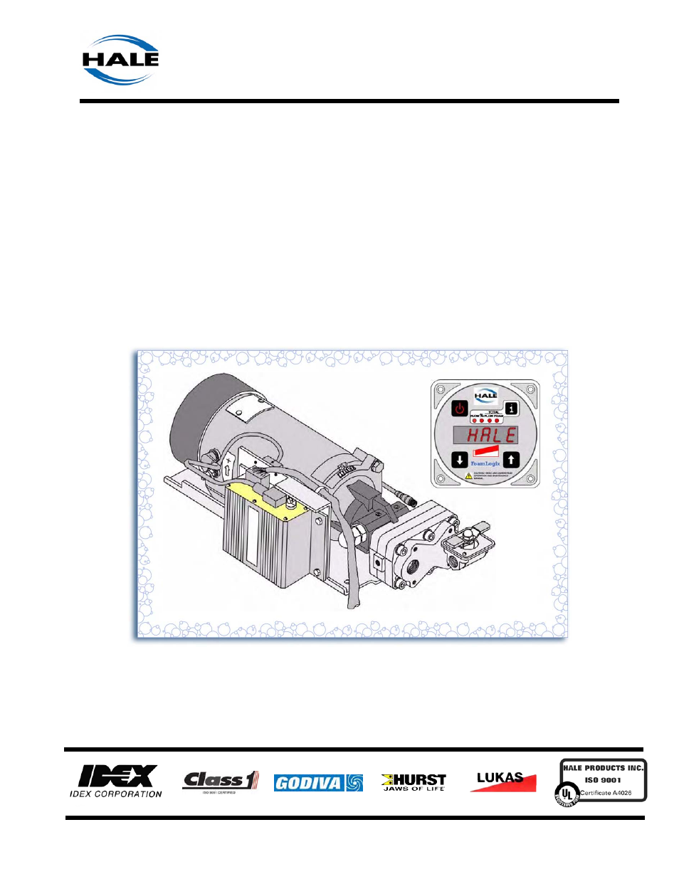
Hale FoamLogix 6.5 User Manual
Foamlogix, Installation and operations manual
This manual is related to the following products:
Table of contents
Document Outline
- FoamLogix 3.3/5.0/6.5 Electronic Foam System, p/n: 029-0021-68-0, Rev-A
- NOTICE !
- Contents
- How to use this manual
- 1 Safety Precautions
- 1 System Overview
- 2.1 Rotary Gear Pump
- 2.2 Control Unit
- 2.3 Water FLow Sensor
- 2.4 Feed Back Sensor
- 2.5 Tank Selector Valves
- 2.6 Low Pressure Strainer
- 2.7 Ordering Information
- 2.8 Hale Foam System Specifications
- 2.9 System Configuration
- 2.10 Cable Harness
- 2.11 Dual Foam Concentrate Tank System Options
- 2.12 Dual Foam Concentrate Tank Options
- 2.13 Single Foam Concentrate Tank Options
- 2.14 Strainer Options
- 2.15 Low Tank Level Sensor Options
- 2.16 Flow Sensors
- 2.17 Check Valve Manifolds
- 2.18 Remote Activation Switch Option
- 2.19 Check Valves, Flanges, Gaskets
- 2.20 Elbows and Mini Manifolds
- 2.21 Hale Foam System Layout Drawings
- Figure 2-10: Typical Single Foam Concentrate Tank
- Figure 2-11: Single Foam Tank with MST and In-Line Strainer/Valve Assembly
- Figure 2-12: Single Foam Tank with MST and FS Series Strainers
- Figure 2-13: Dual Foam Concentrate Tanks, with MDT II and In-Line Strainer/Valve Assembly
- Figure 2-14: Dual Foam Concentrate with MDT II and FS Series Strainer Assembly
- Figure 2-15: Dual Foam Concentrate Tanks, with ADT and In-Line Strainer/Valve Assemblies
- Figure 2-16: Dual Foam Concentrate Tanks with ADT and FS Series Strainer Assemblies
- 3 Installation
- 3.1 Foam Pump and Motor Assembly
- 3.2 Foam Concentrate Strainer
- 3.3 Control Unit / Instruction Placard
- 3.4 Installer Supplied Components
- Foam Concentrate Suction Hose
- Foam Concentrate Discharge Hose
- Foam Concentrate Bypass Hose
- Check Valves
- Flushing Water Hose
- Foam Discharge Drains
- Electrical Requirements
- FoamLogix Display
- Foam Concentrate Tanks(s)
- Foam Pump Mounting
- Plumbing Installation
- Water and Foam Solution Plumbing
- Optional Hale Piping Components
- “Waterway” Check Valves
- Foam Pump Flush System
- Foam Concentrate Plumbing
- Foam Strainer Connection (In-Line Strainer/Valve)
- FS Series Strainer
- Foam Concentrate Injection Hose
- Bypass Hose Connection
- ADT Option Air Connections
- 3.5 System Plumbing Diagrams
- Figure 3-25: Typical Single Foam Concentrate Tank
- Figure 3-26: Typical Single Foam Tank with MST and In-Line Strainer/Valve Assembly
- Figure 3-27: Typical Single Foam Tank, with MST and FS Series Strainers
- Figure 3-28: Single Foam Tank with MST II and In-Line Strainer/Valve Assembly
- Figure 3-29: Typical Single Foam Tank with MST II and FS Series Strainers
- Figure 3-30: Typical Single Foam Tank with ADT and In-Line Strainer/Valve Assemblies
- Figure 3-31: Typical Dual Foam Tanks, with ADT and FS Series Strainer Assemblies
- 3.6 Electrical
- 3.7 Start Up Check List
- 3.8 Installation and Delivery Check List
- 3.9 System Installer Start-UP
- 4 User Setup and Calibration
- 5 Operation
- 6 Maintenance
- 7 Troubleshooting
- Appendix A: Foam Concentrate Compatibility
- Express Warranty
- 8 Illustrated Parts Breakdown
- General
- Abbreviations
- 8.1 Air Dual Tank Valve (ADT) Option
- 8.2 Harness Components
- 8.3 Dual Foam Concentrate Tank Options
- 8.4 Single Foam Concentrate Tank Options
- 8.5 Low Tank Level Sensor Options
- 8.6 Flow Sensors
- 8.7 Main Cable Harness, Single and Dual Tank
- 8.8 Check Valve Manifolds
- 8.9 Remote Activation Switch Option
- 8.10 Check Valves, Flanges, Gaskets
- 8.11 Elbows and Mini Manifolds
- Plate Draawings
- Return HOME Page
- EXIT