Figure 3-44: simulated flow mode display – Hale FoamLogix 6.5 User Manual
Page 107
107
FoamLogix 3.3 / 5.0 / 6.5 Installer / Operations Manual
p/n: 029-0021-68-0
Sta rt -Up Chec k L is t
❑
5.
Place the BYPASS valve in the BYPASS position to check foam pump
operation. Place a calibrated five gallon container at the discharge of
the bypass hose.
6.
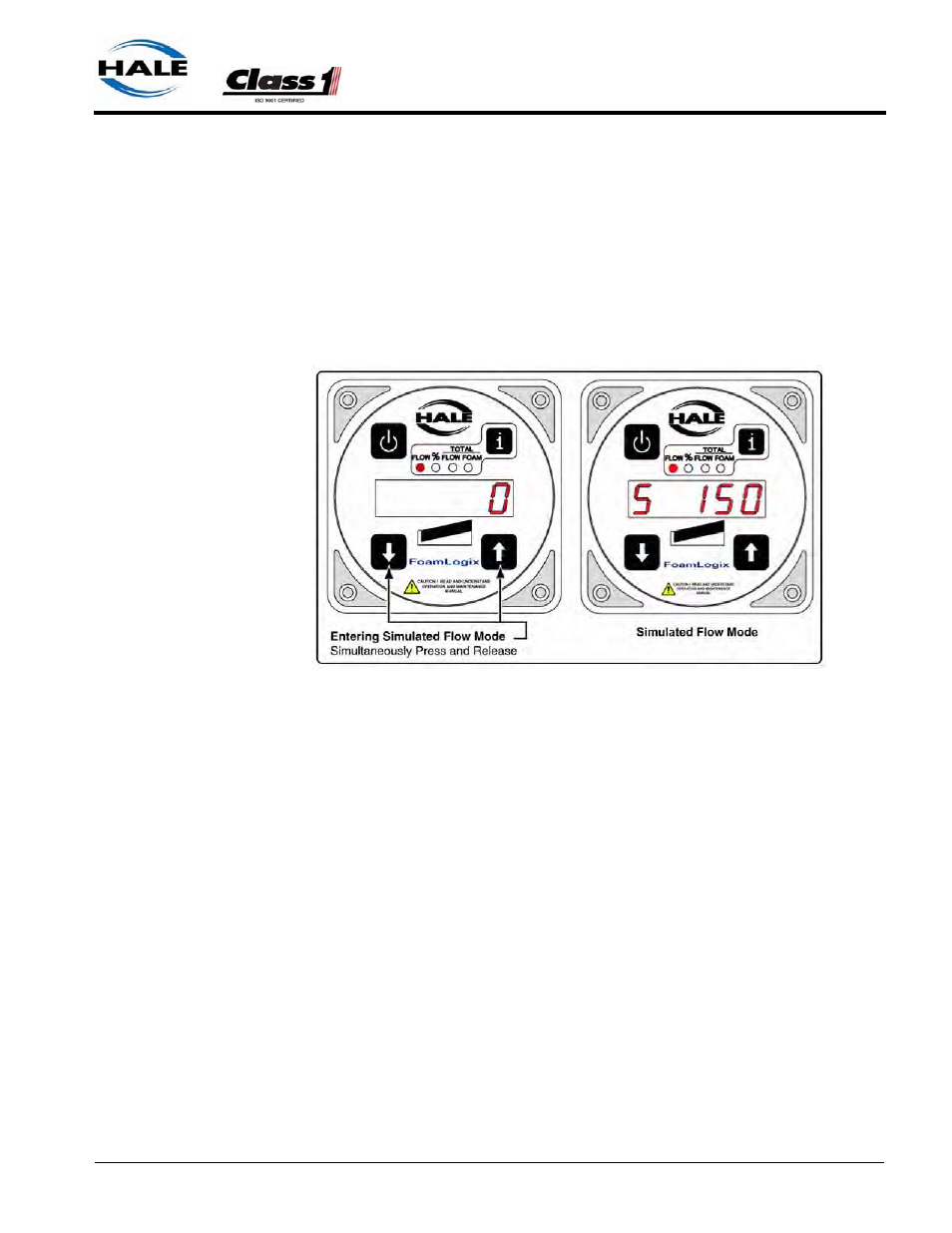
Place the system in simulated flow mode by selecting the FLOW display
and pressing both and buttons simultaneously. Set simulated
flow value to 100 GPM by pressing the or buttons. (See Figure 3-
44: “Simulated Flow Mode Display.”)
Figure 3-44: Simulated Flow Mode Display
7.
The display show S at the left most position to indicate the simulated
flow mode is selected.
8.
Press the SELECT DISPLAY button until the LED under % FOAM illu-
minates. Set foam concentrate injection rate to 1.0 by pressing the
or buttons.
9.
Press the SELECT DISPLAY button until the LED under TOTAL FOAM
illuminates.
10.
Engage the Hale FoamLogix system by pressing the ON button.
Observe the discharge of the bypass hose to make sure the foam pump
is operating.
11.
After one minute press the
i
button to stop the foam pump. There
should be approximately one gallon of water in the container and
TOTAL FOAM reading on the display should show approximately 1.0.