Figure 4-12: exit and save calibration, Relief valve, Figure 4-13: relief valve – Hale FoamLogix 6.5 User Manual
Page 119
Se tup and Cal ibration
❑
119
FoamLogix 3.3 / 5.0 / 6.5 Installer / Operations Manual
p/n: 029-0021-68-0
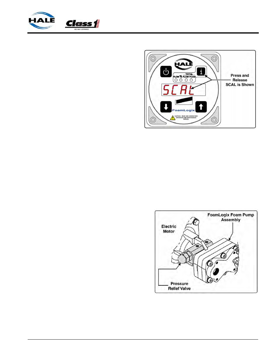
4. The display shows
SCAL for several sec-
onds then cycles
through the start-up
sequence followed by
the flow display O.
(See Figure 4-12: “Exit
and Save Calibration.”)
5. This completes verifi-
cation and adjustment
of the system. The
Hale FoamLogix sys-
tem is now ready to be
placed in service.
Relief Valve
The pressure relief valve is factory tested and set to
❑
Model 3.3 - 350 PSI (24 BAR)
❑
Model 5.0 - 200 PSI (14 BAR)
❑
Model 6.5 - 200 PSI (14 BAR)
(See Figure 4-13: “Relief
Valve.”)
During normal installation
and operation, the relief
valve does not require
adjustment.
If adjustment is necessary
during field installation,
contact Hale Products Inc.
at 610-825-6300 for Relief
Valve Service information.
Figure 4-12: Exit and Save Calibration
Figure 4-13: Relief Valve