Figure 3-33: dual tank electrical harness overview, Control / display unit – Hale FoamLogix 6.5 User Manual
Page 88
❑ Electrical Installation
88
FoamLogix 3.3 / 5.0 / 6.5 Installer / Operations Manual
p/n: 029-0021-68-0
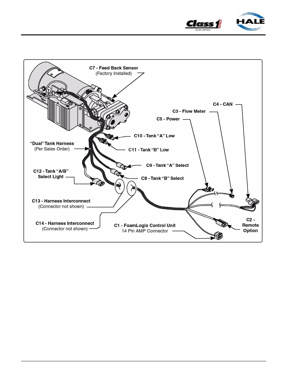
Figure 3-33: Dual Tank Electrical Harness Overview
Control / Display Unit
The control/display unit mounts in the operator panel of the apparatus. The
display is secured with four #10 socket head screws. (See Figure 3-34:
“Control/Display Unit Mounting Dimensions” on page 89.)
The display requires a 7.00” (178mm) minimum clearance from the back of
the operator panel to allow proper cable connection. Once the control unit
is mounted on the operator panel, attach the 14 pin AMP connector on the
cable assembly to the back of the display. For harness overview, see Sec-
tion 8 “ Drawing Package,” on page 155. Also see Figure 3-35: “Distribution
Box Connections” on page 90.