Hale FoamLogix 6.5 User Manual
Page 89
89
FoamLogix 3.3 / 5.0 / 6.5 Installer / Operations Manual
p/n: 029-0021-68-0
Ele c tri ca l Ins ta lla tion
❑
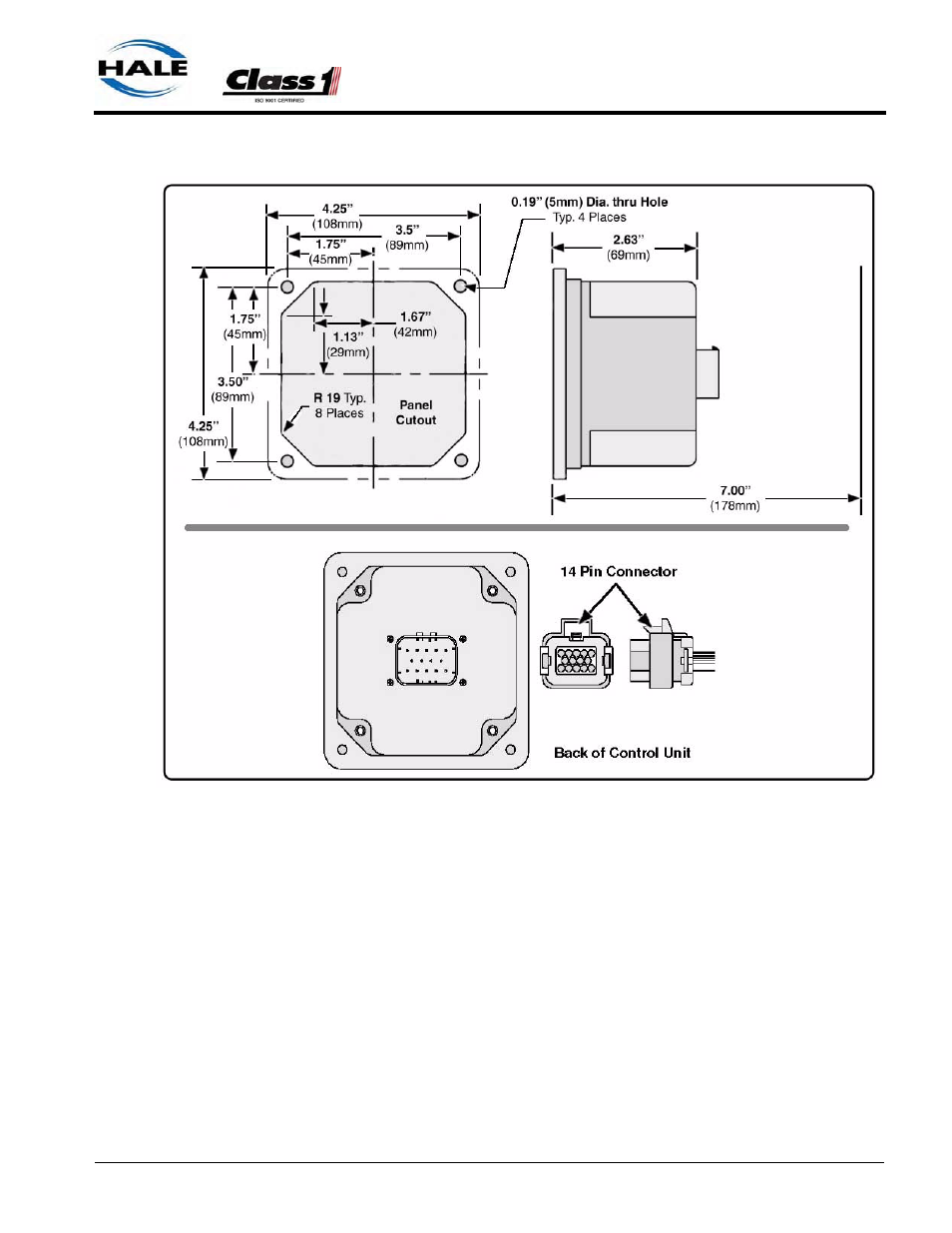
Figure 3-34: Control/Display Unit Mounting Dimensions
Notes: Ensure that the panel where the control unit is mounted has an adequate
ground. For stainless steel and vinyl coated panels a ground strap, 1/2” (13mm)
wide, must be attached from one of the four screws securing the control unit in
place to the frame of the fire truck to ensure adequate grounding.
Add a service loop to avoid strain on the wires or connectors during body
and frame flex. Also see Figure 3-36: “Extra Cable Storage” on page 92.
Control / Display Unit Connection
The main control cable harness connects to the 14-pin AMP connector or
pigtail on the back of the control unit. For harness overview, see Section 8 “
Drawing Package,” on page 155. Also see Figure 3-34: “Control/Display
Unit Mounting Dimensions” on page 89.