Hale FoamLogix 6.5 User Manual
Page 100
❑ Electrical Installation
100
FoamLogix 3.3 / 5.0 / 6.5 Installer / Operations Manual
p/n: 029-0021-68-0
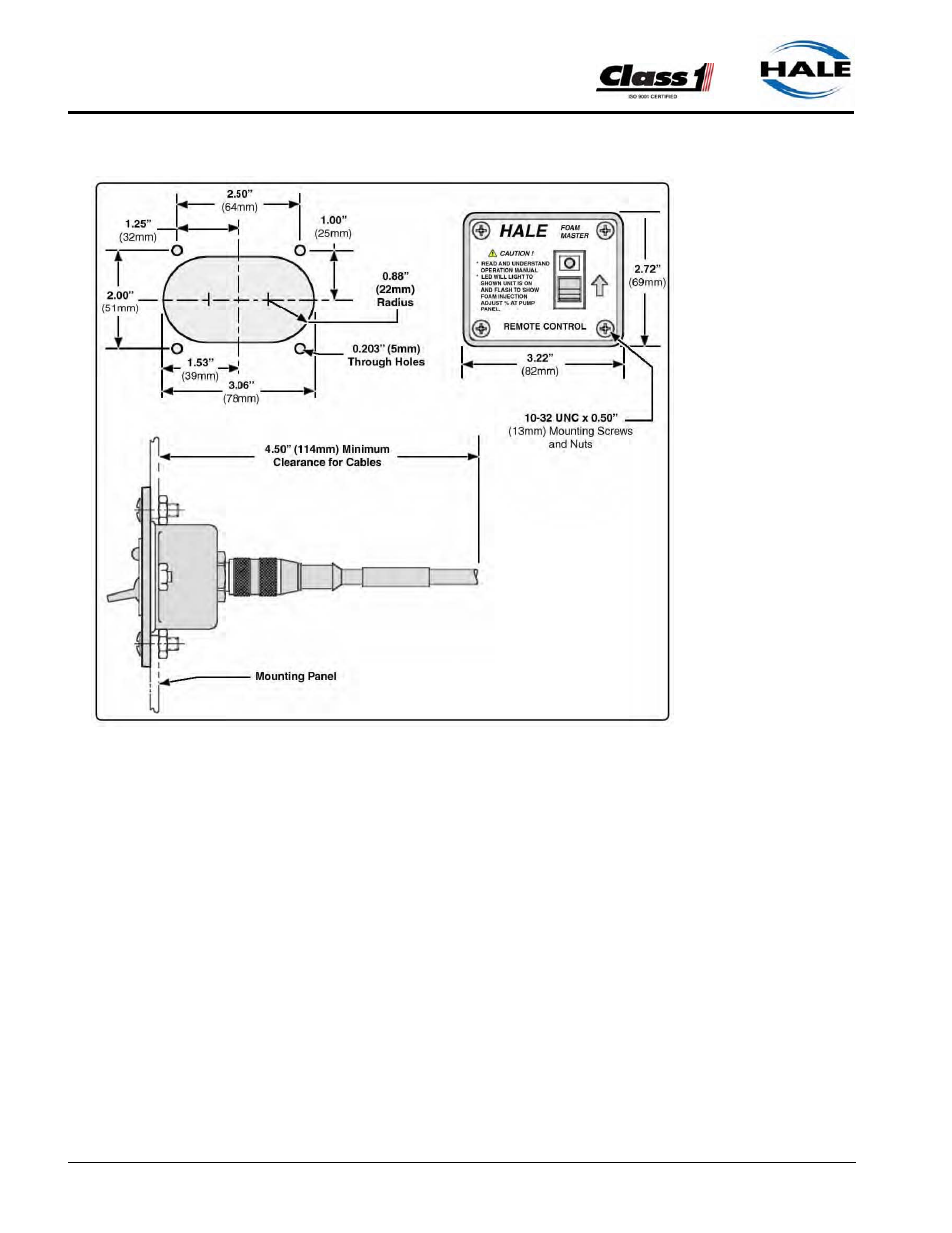
Figure 3-41: Remote Activation Switch Installation Dimensions
1.
Insert switch assembly through the panel cutout and secure to using the
#10-24 UNC x 1/2” (13mm) screws and nuts provided.
Note: When making cable connections, make sure the cable is routed by the
shortest most direct route. A maximum of 40 feet (12 meters) of remote cable
may be used.
2.
Connect the remote activation switch cable from the main cable harness
connector C2. (See Figure 3-32: “Single Tank Electrical Harness Over-
view” on page 87.) Also see Figure 3-33: “Dual Tank Electrical Harness
Overview” on page 88.
This manual is related to the following products: