Strainer/valve assemblies – Hale FoamLogix 6.5 User Manual
Page 83
83
FoamLogix 3.3 / 5.0 / 6.5 Installer / Operations Manual
p/n: 029-0021-68-0
Plum bi ng Ins ta lla tion
❑
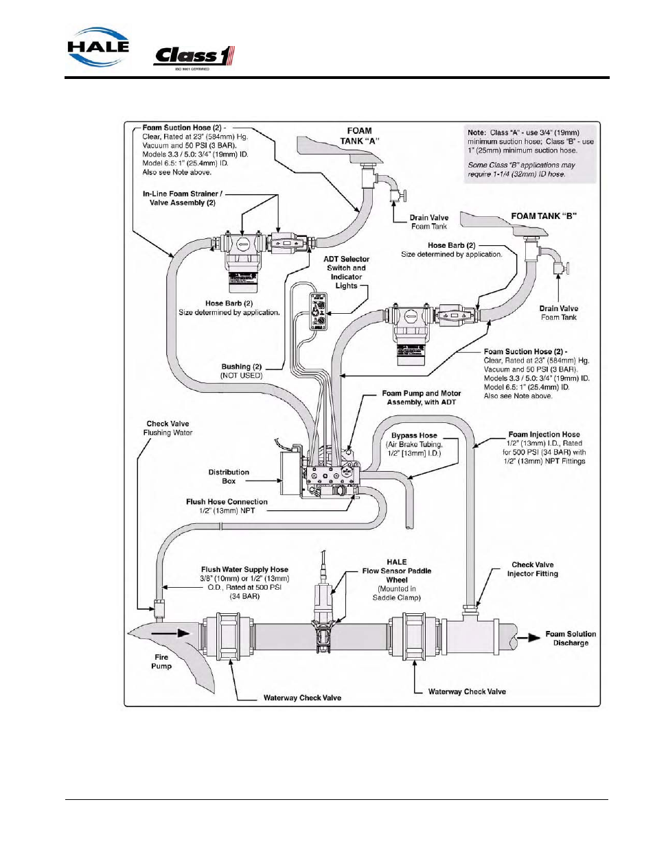
Figure 3-30: Typical Single Foam Tank with ADT and In-Line Strainer/Valve Assemblies
(For barb fitting sizes, see Figure
3-14: “In-Line Strainer/Valve
Installation” on page 67.)
(For barb fitting sizes, see Figure
3-14: “In-Line Strainer/Valve
Installation” on page 67.)
This manual is related to the following products: