Autopilot connection, External nmea connection, C-com gsm plus connection – Seiwa Starfish 2nd Edition User Manual
Page 85: 87 user manual
87
User Manual
Autopilot Connection
NMEA0183/180/180CDX/INPUT+
SIGNAL RETURN
AUTOPILOT DEVICE
FUNCTION
BLACK
RED
WHITE
GREEN
YELLOW
BROWN
GRAY
ORANGE
PINK
BLUE
PWR-/GND/COMMON
POWER+ 10-35Vdc
INPUT 1+
COMMON
OUTPUT 1+
INPUT 2+
OUTPUT 2+
INPUT 3+
OUTPUT 3+
COMMON
QUICK DISCONNECT BRACKET CABLE
DESCRIPTION
WIRE COLOR
Autopilot Connections on Port 2
External NMEA Connection
NMEA0183 OUTPUT+
NMEA0183 INPUT+
SIGNAL RETURN
NMEA0183 DEVICE
FUNCTION
BLACK
RED
WHITE
GREEN
YELLOW
BROWN
GRAY
ORANGE
PINK
BLUE
PWR-/GND/COMMON
POWER+ 10-35Vdc
INPUT 1+
COMMON
OUTPUT 1+
INPUT 2+
OUTPUT 2+
INPUT 3+
OUTPUT 3+
COMMON
QUICK DISCONNECT BRACKET CABLE
DESCRIPTION
WIRE COLOR
External NMEA Connections on Port 1
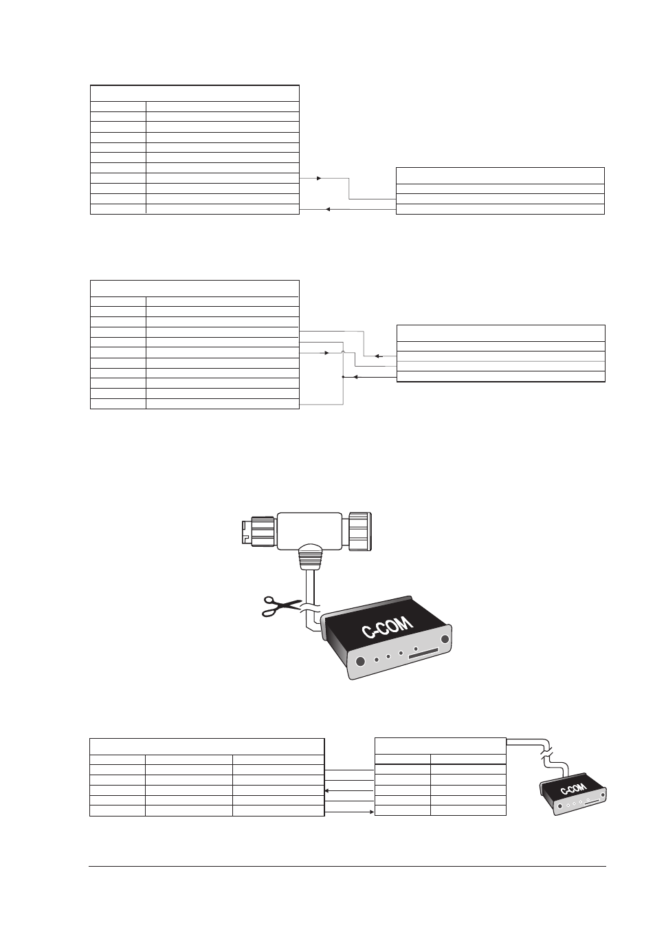
C-COM GSM Plus Connection
To connect the modem C-COM to the chart plotter with quick disconnect bracket
follow the procedure:
1. Cut the C-COM cable about 1.96" [5 cm] from the "T" connector:
C-COM Cable
2. Connect the wires to the quick disconnect bracket cable as follows:
QUICK DISCONNECT BRACKET CABLE
DESCRIPTION
WIRE COLOR
BLACK
RED
WHITE
GREEN
YELLOW
POWER SUPPLY GND
POWER SUPPLY+
C-COM
C-COM
C-COM
POWER GND
POWER +10-35Vdc
INPUT 1+
COMMON
OUTPUT 1+
FUNCTION
C-COM GSM Plus CABLE
WIRE COLOR
BLACK
RED
WHITE
GREEN
YELLOW
GND
POWER SUPPLY+
C-COM TX+
C-COM TX-
C-COM RX+
FUNCTION
Connection for the Port 1