Festo Модуль перемещения HSP User Manual
Page 44
HSP−...−AP/A S
Festo HSP−...−AP/AS 0508a English
44
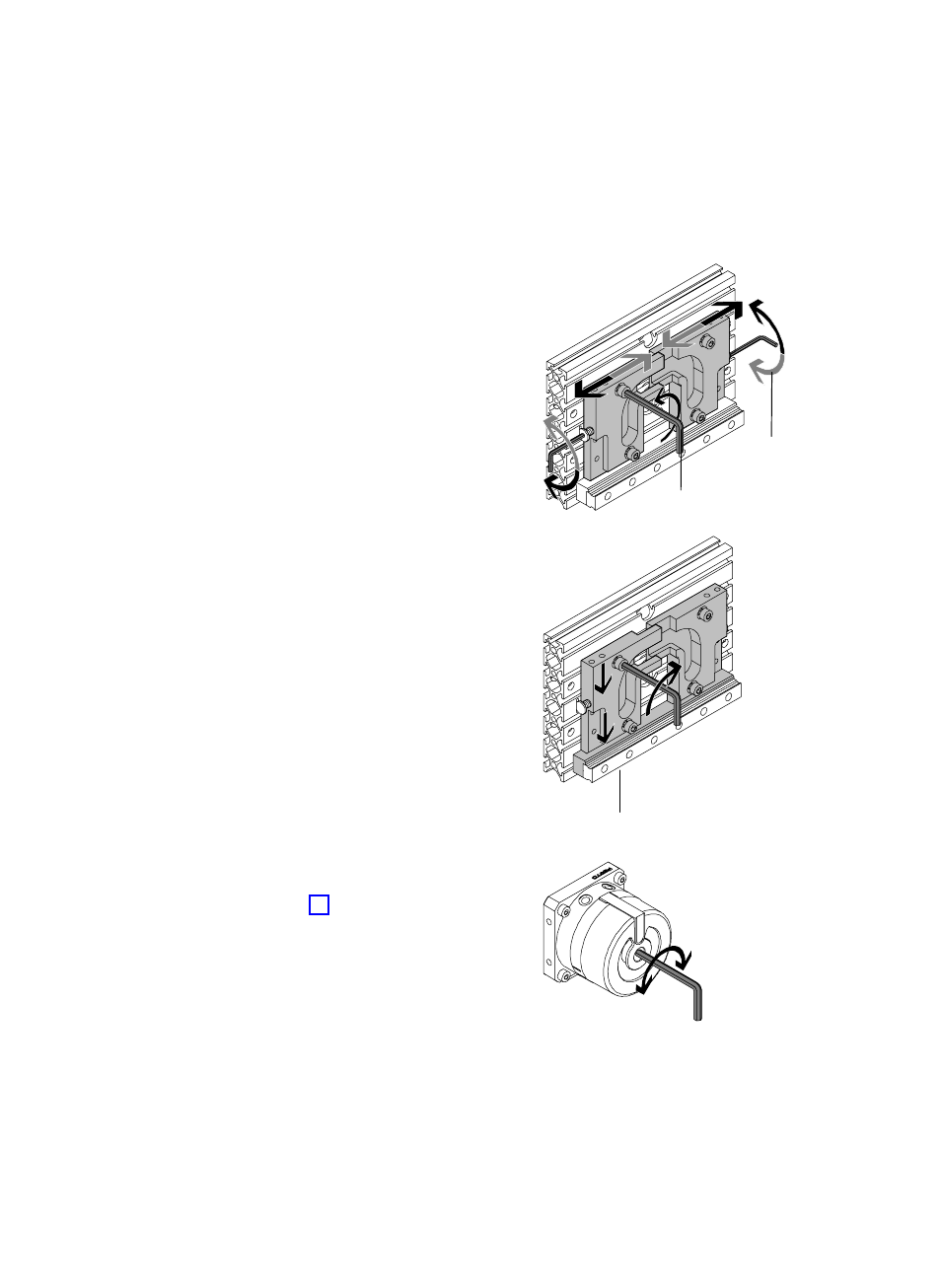
5. Loosen the fastening screws (C) of the
right−hand and left−hand link parts just
enough to enable the link parts to be
shifted.
6. Turn the adjusting screws (D) until the link
parts have reached the desired receive or
release position.
If side plates are fitted, you can set the
adjusting screws with a hexagon socket
screw key through the holes in the side
plates.
Alignment free of offset:
7. Press the link parts down vertically
against the aluminium stop strip (E) of the
horizontal guide rail, while you tighten the
fastening screw of the link parts (tightenĆ
ing torque: 6 Nm).
S
Carry out a manual check of the following
after each adjustment (without pressurizĆ
ing the drive):
ć Has the desired end position been
reached?
ć Are the link parts aligned without
offset?
S
In order to do this, swing the moveable
mass into the end positions.
ć by hand or
ć with a hexagon socket screw key on
the drive (Fig. 16).
S
When doing this, check that the double
rollers run smoothly in the path guide.
S
If necessary, correct the alignment of the
link parts.
Fig. 14
(D)
(C)
Fig. 15
(E)
Fig. 16