Installing breakers on the ats panel bus – American Power Conversion 250 A User Manual
Page 84
How to Add Sub-Feed Output Distribution Circuit Breakers to the ATS
74
InfraStruXure Power Generation System
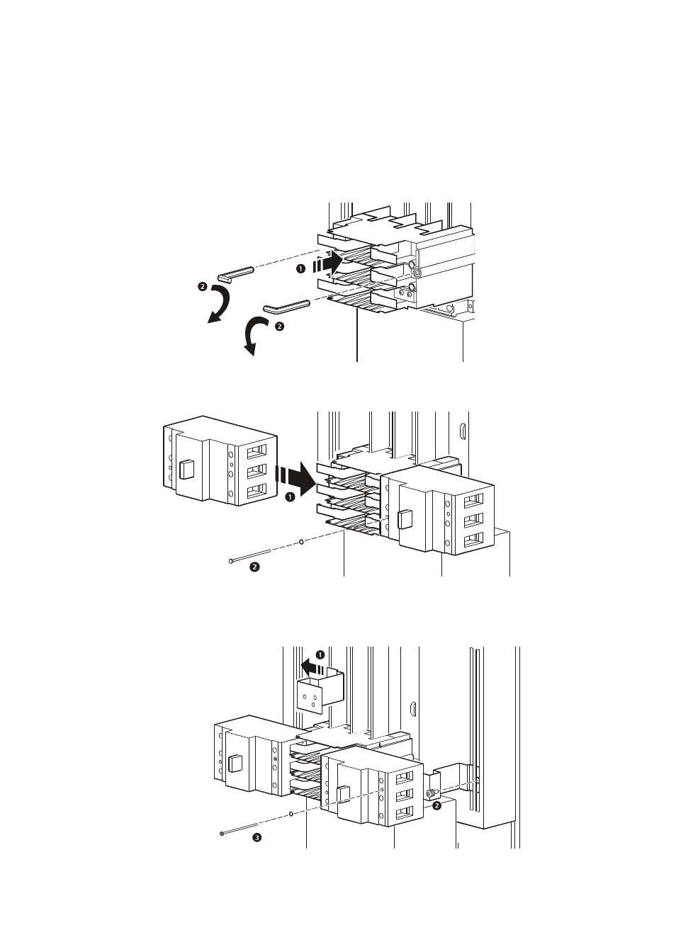
Installing breakers on the ATS panel bus
Use the following procedure to install a T1 three-pole breaker assembly on a 250 A ATS panel bus.
The steps are identical for installing the T1 single-pole and T3 three-pole breakers.
1. Attach the adapter module to the ATS panel bus
(
)
, and secure it in place using an Allen
wrench to turn the module locks
(
)
.
2. Snap the circuit breakers onto the adapter module’s bus
(
)
. Lock in place using a Phillips
screwdriver to tighten an M4×70 screw
(
)
.
3. Attach the breaker brackets to slots in the panel board frame
(
)
. Secure using a T25 Torx
driver to tighten an M6×12 Torx screw
(
)
. Attach each breaker to its appropriate bracket
using a Phillips screwdriver to tighten an M4×70 screw
(
)
.
- 5000VA (25 pages)
- MX28B-400 (46 pages)
- CTEG4-240MB-5 (7 pages)
- 200/208 V (52 pages)
- VS 100 (54 pages)
- SMARTUPS 700 (60 pages)
- AP7562J (24 pages)
- 100VAC (18 pages)
- Smart-UPS VT (56 pages)
- 1400XLT (30 pages)
- 350/550 (2 pages)
- SURTA1500XLJ (16 pages)
- RT-UXI (20 pages)
- 2200 VA (17 pages)
- 208 Vac (17 pages)
- 1500VA (18 pages)
- Smart-UPS (36 pages)
- 60-80kW 208/480V (34 pages)
- 420 (3 pages)
- 220 VAC (21 pages)
- 350 (2 pages)
- AP9215 (20 pages)
- Back-UPS CS 500 (2 pages)
- PDU (54 pages)
- Airless Paint Sprayer 68001 (24 pages)
- AP7610 (16 pages)
- AP7902 AP7911 (26 pages)
- UPS (2 pages)
- RT XLI/XLICH (34 pages)
- 990-2233A (19 pages)
- 208/220 (48 pages)
- NS 600 (2 pages)
- SYMF800KH (54 pages)
- 20-30 kVA 480V (4 pages)
- 100 VAC (25 pages)
- 750 (17 pages)
- 3000 (23 pages)
- MX28B200 (61 pages)
- RS 1000 (2 pages)
- 200-240 VAC (21 pages)
- 5000RMB (23 pages)
- 480kW400V (32 pages)
- AP9825I (1 page)
- 250/450 (2 pages)
- SUA48RMXLBP3U (8 pages)