Automatic operation control panel, User connection plate, User connection plate” on – American Power Conversion 250 A User Manual
Page 26: Automatic operation control
ATS Component Details
16
InfraStruXure Power Generation System
Automatic operation control panel
For more detailed information concerning Automatic Operation of the InfraStruXure Power
Generation System, see “Automatic Operation” on page 19.
User connection plate
For location and description of the user connection plate, see number 2 on page 11. For clarity, the
plate is shown facing upwards, as opposed to its factory-installed downward-facing position. The
user interface board, the primary component on the plate, accepts most connections described below.
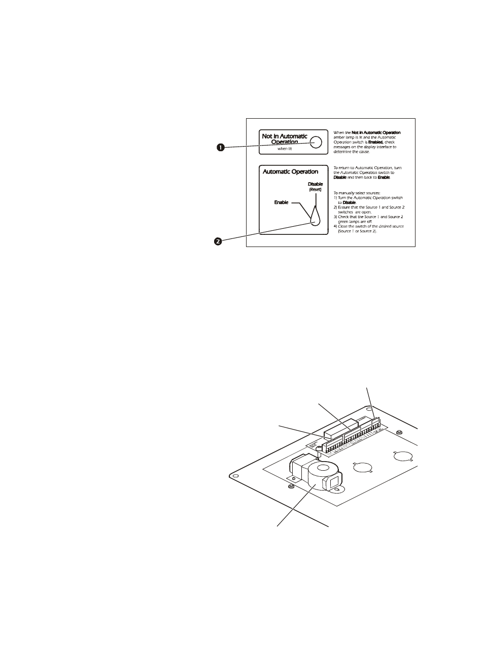
The Not in Automatic Operation
LED is lit when the ATS is NOT
in automatic operation. This
typically occurs when the
automatic operation switch is set
to Disable. In rare instances, the
Not in Automatic Operation
LED will be lit when the
automatic operation switch is in
the Enable position (see page 21
for more information).
Use the Automatic Operation switch to select whether the generator should automatically
turn on after a loss of power.
Connect the ATS to either the network
or the InfraStruXure Manager through
the surge-protected ethernet port. This
port protects your network connection
from power surges.
The user interface board has four input
contact connections for monitoring
Normally Open (NO) or Normally
Closed (NC) dry contacts (see page 46
and page 61 for more information).
The user interface board has four relay
output connections to accommodate
NO or NC dry contacts (see page 46 and
page 61 for more information).
Connect an Emergency Power-Off switch at one of the three EPO connection choices:
24 VDC, 24 VAC, or contact closure (see page 63 for more information).