How to connect an epo switch to the ats, 64 infrastruxure power generation system – American Power Conversion 250 A User Manual
Page 74
How to Connect an EPO Switch to the ATS
64
InfraStruXure Power Generation System
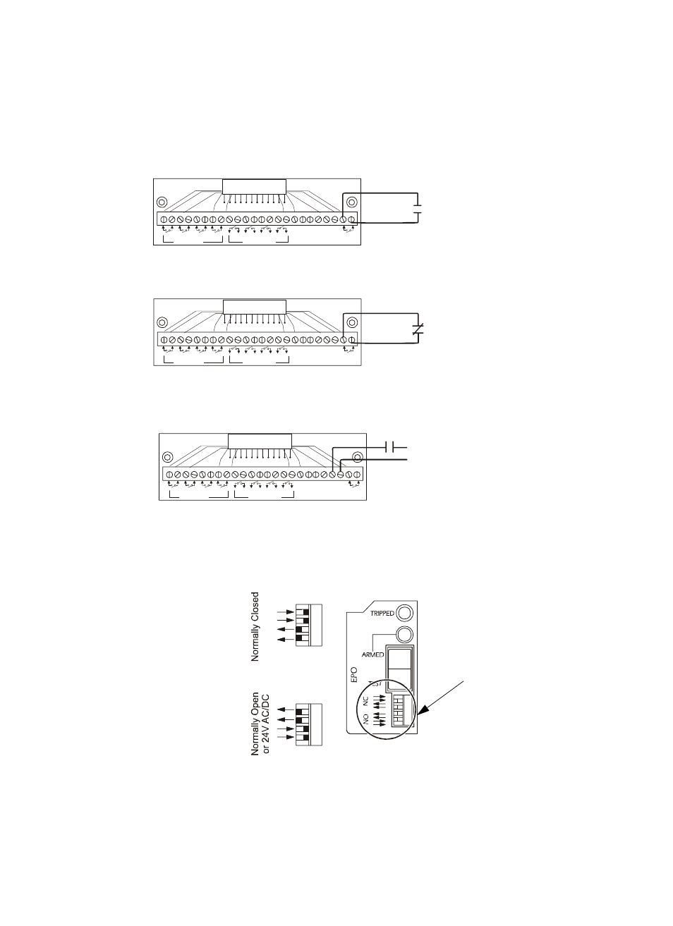
Connect an EPO switch to the user interface board and test the switch
1. Connect the switch to the EPO connection terminals on the user interface board. Read the label
next to the terminal block to determine which terminals correspond to your signal type:
– Contact Closure—Normally Open
– Contact Closure—Normally Closed
– 24VAC/VDC—Normally Open
2. Verify that the EPO DIP switches on the ATS monitoring unit are configured properly for your
signal type. The labels above the switches and the figure below show the correct settings for
both the Normally Open (NO) and Normally Closed (NC) configurations.
1
2
3
4
AT
S
E
N
ATS
0
AT
S
1
ATS
2
EPO
Contact
– +
EPO 24V
AC/DC
Contact Inputs
Contact Outputs
USER INTERFACE
© 2001 APC
MADE IN USA
External set of Normally Open
Voltage-free Contacts
1
2
3
4
AT
S
E
N
AT
S
0
AT
S
1
AT
S
2
EPO
Contact
– +
EPO 24V
AC/DC
Contact Inputs
Contact Outputs
USER INTERFACE
© 2001 APC
MADE IN USA
External set of Normally Open
Voltage-free Contacts
1
2
3
4
AT
S
E
N
AT
S
0
AT
S
1
AT
S
2
EPO
Contact
– +
EPO 24V
AC/DC
Contact Inputs
Contact Outputs
USER INTERFACE
© 2001 APC
MADE IN USA
24 VAC or 24 VDC
External set of
Normally Open Voltage-free Contacts
Power Supply
Location of switches
on ATS monitoring unit