Ats panel board, left side – American Power Conversion 250 A User Manual
Page 23
Smart Distribution Panel with ATS
InfraStruXure Power Generation System
13
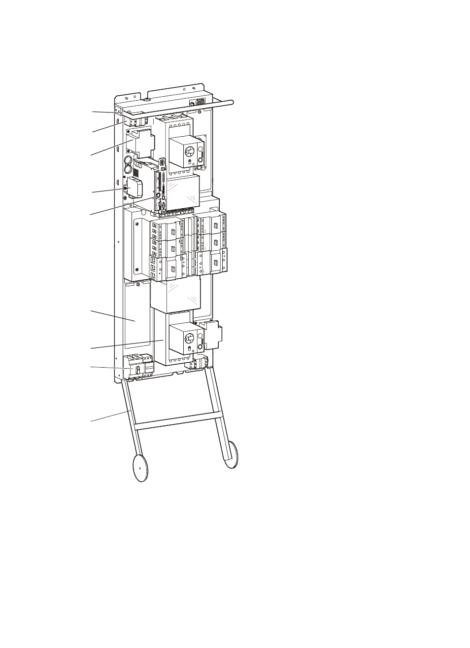
ATS panel board, left side
The handle aids removal of the panel board
assembly from the ATS enclosure. At least
two people are required to remove the panel
board assembly (refer to the Electrical
Installation Manual for instructions).
The Source 1 fuse block regulates input to
the Source 1 control transformer for
subsequent powering of the Source 1
motorized switch and ATS monitoring unit.
The Source 1 control transformer outputs
120 VAC and 18 VAC to the Source 1
motorized switch and the ATS monitoring
unit after stepping down the 480 V or 208 V
input.
The communication converter allows the
generator and the ATS to communicate.
The ATS monitoring unit houses a central
board assembly that communicates with
several monitoring boards located
throughout the ATS (see
unit” on page 17 for detailed information).
Behind this access panel is the ATS interface
circuit board. Use a Phillips or standard
screwdriver to remove the panel.
The Source 2 input switch accepts input
wires from the generator (refer to the
Electrical Installation Manual for
connection instructions).
WARNING: Only a certified electrician
should connect the generator to the ATS!
This switch and fuse block regulate the 120 VAC supply to the generator for powering the
block heater and battery charger.
The wheel extensions on the panel board assembly allow removal of the assembly during
installation. Removing the panel board assembly makes it easier to pull wires into the ATS.