Dip s, Nstalling, Eter – Red Lion PAX2D User Manual
Page 5: Etting, Witches, Installation, Installation environment
5
1.0 i
nsTalling
The
m
eTer
2.0 s
eTTing
The
dip s
wiTChes
Installation
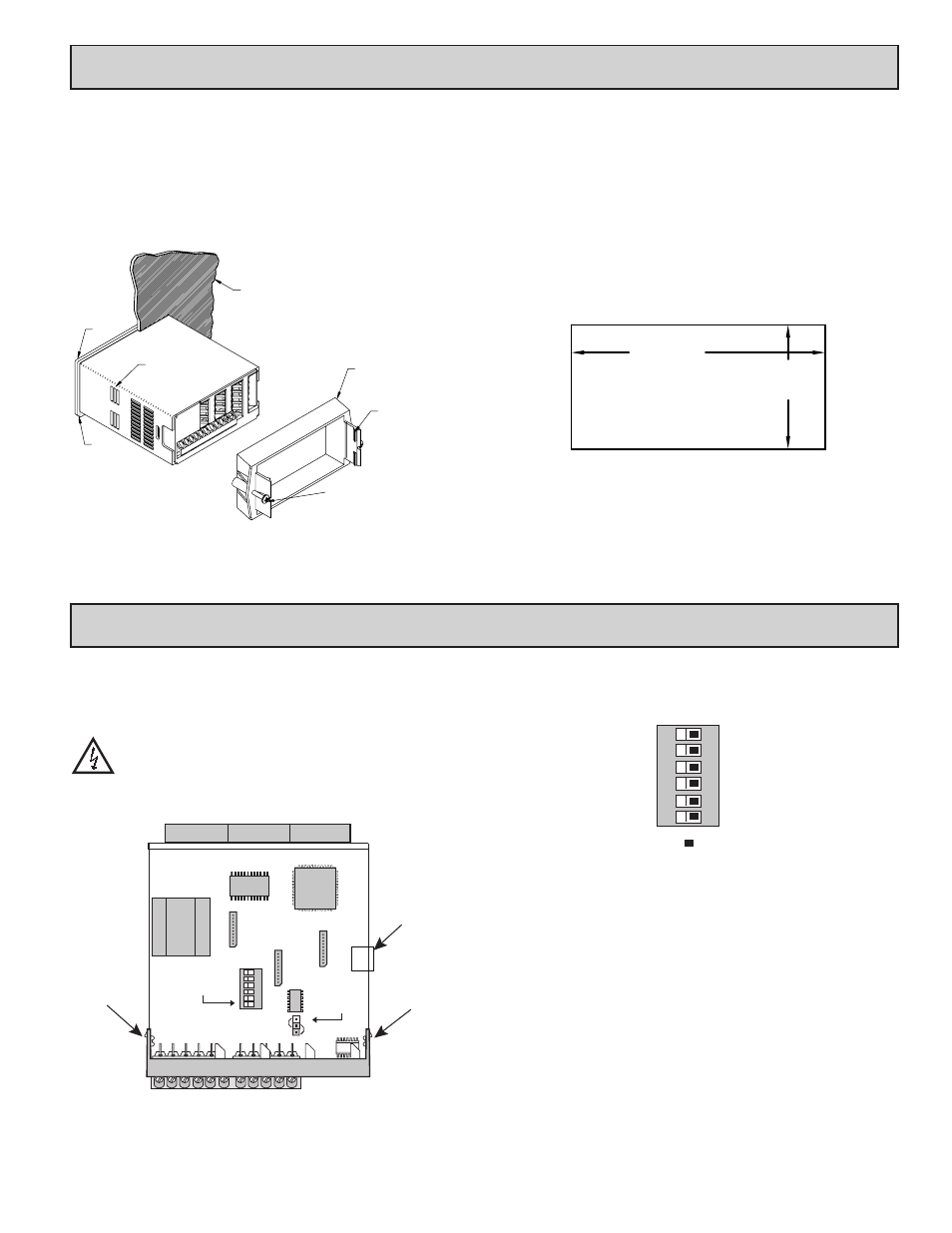
The PAX2D meets NEMA 4X/IP65 requirements when properly installed.
The unit is intended to be mounted into an enclosed panel. Prepare the panel
cutout to the dimensions shown. Remove the panel latch from the unit. Slide the
panel gasket over the rear of the unit to the back of the bezel. The unit should
be installed fully assembled. Insert the unit into the panel cutout.
While holding the unit in place, push the panel latch over the rear of the unit
so that the tabs of the panel latch engage in the slots on the case. The panel latch
should be engaged in the farthest forward slot possible. To achieve a proper seal,
tighten the latch screws evenly until the
unit is snug in the panel (Torque to
approximately 7 in-lbs [79N-cm]).
Do not over-tighten the screws.
Installation Environment
The unit should be installed in a location that does not exceed the operating
temperature and provides good air circulation. Placing the unit near devices that
generate excessive heat should be avoided.
The bezel should only be cleaned with a soft cloth and neutral soap product.
Do NOT use solvents. Continuous exposure to direct sunlight may accelerate the
aging process of the bezel.
Do not use tools of any kind (screwdrivers, pens, pencils, etc.) to operate the
keypad of the unit.
PANEL
LATCHING
SLOTS
BEZEL
PANEL
GASKET
PANEL
LATCH
LATCHING
TABS
PANEL
MOUNTING
SCREWS
-.00
(92 )
-.0
+.8
3.62
+.03
(45 )
1.77
-.0
+.5
-.00
+.02
PANEL CUT-OUT
To access the switches, remove the meter base from the case by firmly
squeezing and pulling back on the side rear finger tabs. This should lower the
latch below the case slot (which is located just in front of the finger tabs). It is
recommended to release the latch on one side, then start the other side latch.
Warning: Exposed line voltage exists on the circuit boards. Remove
all power to the meter and load circuits before accessing inside of
the meter.
SETTING THE INPUT DIP SWITCHES
The meter has six DIP switches for Input A and Input B terminal set-up that
must be set before applying power.
SWITCHES 1 and 4
LOGIC: Input trigger levels V
IL
= 1.5 V max.; V
IH
= 3.75 V min.
MAG: 200 mV peak input sensitivity; 100 mV hysteresis; maximum voltage:
± 40 V peak (28 Vrms); Input impedance: 3.9 KΩ @ 60 Hz; Must also have
SRC switch ON. (Not recommended with counting applications.)
SWITCHES 2 and 5
SNK.: Adds internal 7.8 KW pull-up resistor to +5 VDC, I
MAX
= 0.7 mA.
SRC.: Adds internal 3.9 KW pull-down resistor, 7.3 mA max. @ 28 VDC,
V
MAX
= 30 VDC.
SWITCHES 3 and 6
HI Frequency: Removes damping capacitor and allows max. frequency.
LO Frequency: Adds a damping capacitor for switch contact bounce. Also
limits input frequency to maximum 50 Hz and input pulse widths to
minimum 10 msec.
Main
Circuit
Board
REAR TERMINALS
FRONT DISPLAY
INPUT SET-UP
DIP SWITCHES
USER
INPUT
JUMPER
1
2
3
4
5
6
SRC
SNK
Finger
Tab
Finger
Tab
USB
Connector
6
5
4
3
2
1
ON
Input B SRC.
Input B LO Freq.
Input B MAG.
Input A LO Freq.
Input A SRC.
Input A MAG.
SNK.
HI Freq.
Logic
HI Freq.
SNK.
Logic
Factory Setting