Scaler, Dec pt, Select – Red Lion PAX2D User Manual
Page 14: Lo-udt, Hi-udt, Hi asn, Hi cap, Lo asn, Lo cap
14
RATE C DISPLAY MULTIPLIER
1
10
100
1000
Set the Display Multiplier to obtain the desired Rate C display resolution. For
Rate C percentage calculations, the result is internally multiplied by 100 to show
percent as a whole number. By using a Display Multiplier of 10, 100 or 1000,
along with the proper decimal point position, percentage can be shown in tenths,
hundredths or thousandths respectively.
RATE C DECIMAL POSITION
0
0.00
0.0000
0.0
0.000
Select the decimal point position for Rate C.
RATE UPDATE PARAMETERS
RATE LOW UPDATE TIME (DISPLAY UPDATE)
0.1
to
999.9
seconds
The Low Update Time is the minimum amount of time between display
updates for all enabled Rate displays. Small Low Update Time values may
increase the possibility of the display indicating an unstable input (jittery
display). The factory setting of 1.0 will update the display at a minimum of
every second.
RATE HIGH UPDATE TIME
0.2
to
999.9
seconds
The High Update Time is the maximum amount of time before the enabled
Rate displays are forced to zero. (For more explanation, refer to Input Frequency
Calculation.) The High Update Time must be higher than the Low Update Time
and higher than the desired slowest readable speed (one divided by pulses per
second). The factory setting of 2.0, will force the display to zero for speeds
below 0.5 Hz or a pulse every 2 seconds.
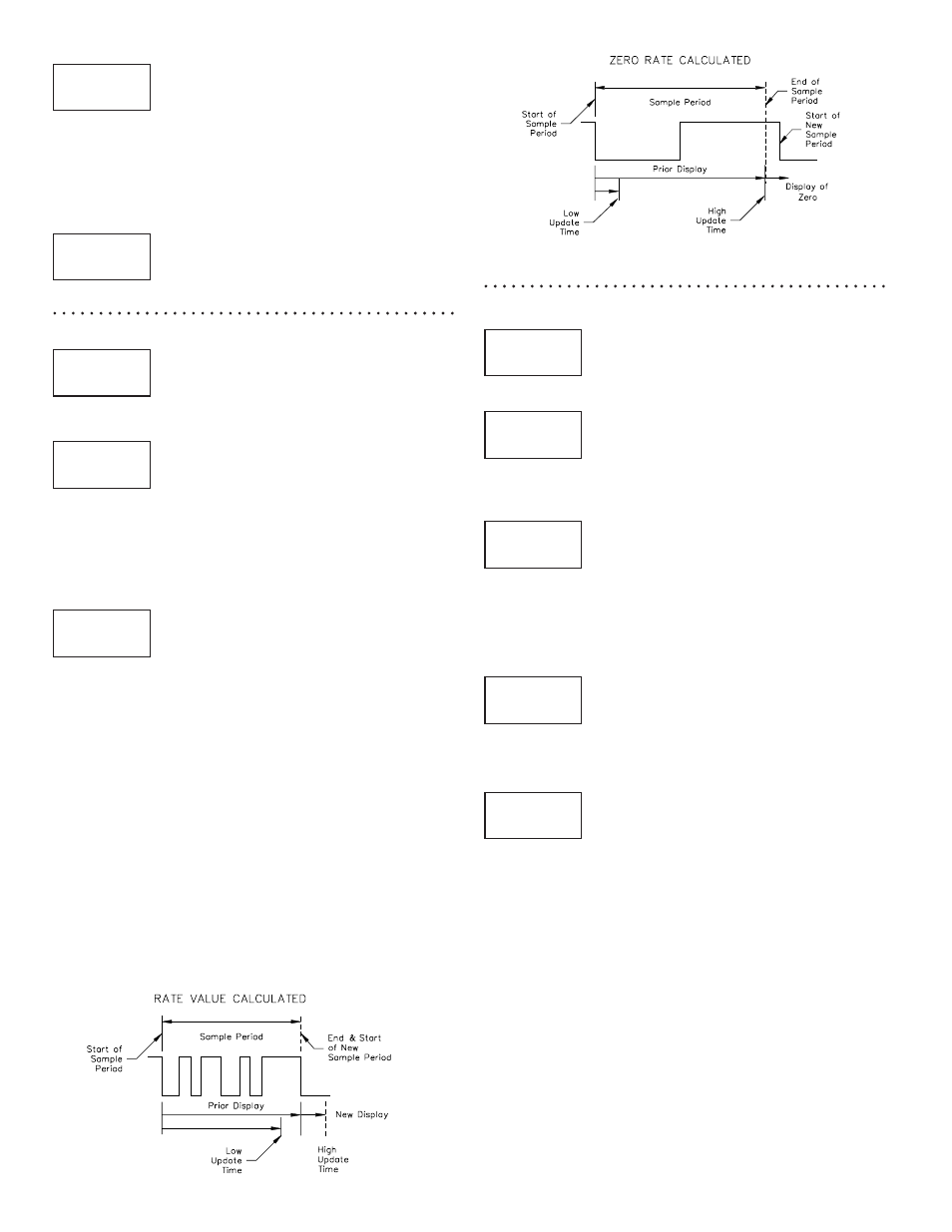
INPUT FREQUENCY CALCULATION
The meter determines the input frequency by summing the number of falling
edges received during a sample period of time. The sample period begins on the
first falling edge. At this falling edge, the meter starts accumulating time
towards Low Update and High Update values. Also, the meter starts accumulating
the number of falling edges. When the time reaches the Low Update Time value,
the meter looks for one more falling edge to end the sample period. If a falling
edge occurs (before the High Update Time value is reached), the Rate display
will update to the new value and the next sample period will start on the same
edge. If the High Update Time value is reached (without receiving a falling edge
after reaching Low Update Time), then the sample period will end but the Rate
display will be forced to zero. The High Update Time value must be greater than
the Low Update Time value. Both values must be greater than 0.0. The input
frequency calculated during the sample period, is then shown as a Rate value
determined by either scaling method.
RATE MAXIMUM/MINIMUM CAPTURE PARAMETERS
MAXIMUM CAPTURE VALUE ASSIGNMENT
RAtE A
RAtE b
RAtE C
Select the Rate display to which the Maximum Capture value is assigned.
MAXIMUM CAPTURE DELAY TIME
0.0
to
999.9
seconds
When the assigned Rate value is above the present Maximum rate value for
the entered amount of time, the meter will capture that Rate value as the new
Maximum value. A delay time helps to avoid false captures of sudden short
spikes.
MINIMUM CAPTURE VALUE ASSIGNMENT
RAtE A
RAtE b
RAtE C
Select the Rate display to which the Minimum Capture value is assigned.
MINIMUM CAPTURE DELAY TIME
0.0
to
999.9
seconds
When the assigned Rate value is below the present Minimum rate value for
the entered amount of time, the meter will capture that Rate value as the new
Minimum value. A delay time helps to avoid false captures of sudden short
spikes.
SCALEr
1
RtC
dEC Pt
0
RtC
SELECt
UPdAtE
Rt
LO-Udt
1.0
SEC
HI-Udt
2.0
SEC
SELECt
Hi-Lo
Rt
Hi ASN
RAtE A
Rt
Hi CAP
1.0
SEC
Lo ASN
RAtE A
Rt
Lo CAP
1.0
SEC