Input, Rate, Dec pt – Red Lion PAX2D User Manual
Page 12: Style, Sc pts, Round, Lo-cut, Rate c, Scaler, Hi-udt
12
SCALING CALCULATION
Each counter has the ability to scale an input signal to a desired display value.
This is accomplished by the counter mode (Cnt x), decimal point (dEC Pt), scale
factor (SC FAC), and scale multiplier (SCALEr). The scale factor is calculated using:
SF (SC FAC) = DDD
(Number of pulses per ‘single’ unit X CMF X SM)
Where:
Number of pulses per ‘single’ unit: pulses per unit generated by the
process (i.e. # of pulses per foot)
CMF: Counter Mode(Cnt x) times factor of the mode 1,2 or 4.
SM: Scale Multiplier (SCALEr) selection of 10, 1, 0.1 or 0.01.
DDD: Desired Display Decimal (1 =1, 1.0 = 10, 1.00 = 100, etc.)
Example:
1. Indicate feet to the hundredths (0.00) with 100 pulses per foot:
Scale Factor would be 100 / (100 x 1 x 1) = 1
(In this case, the scale multiplier and counter mode factor are 1)
2. Indicate feet with 120 pulses per foot: Scale Factor would be 1 / (120 x 1 x 1)
= 0.0083333. (In this case, the scale multiplier of 0.01 could be used: 1 / (120
x 1 x 0.01) = 0.83333 or show to hundredths (0.00): 100 / (120 x 1 x 1) =
0.8333.)
General Rules on Scaling
1. It is recommended that, the scale factor be as close as possible to, but not
exceeding 1.00000. This can be accomplished by increasing or decreasing the
counter decimal point position, using the scale multiplier, or selecting a
different count mode.
2. To double the number of pulses per unit, use counter modes direction X2 or
quad X2. To increase it by four times, use counter mode quad X4. Using these
modes will decrease the allowable maximum input frequency.
3. A scale factor greater than 1.00000 will cause Counter display rounding. In
this case, digit jumps could be caused by the internal count register rounding
the display. The precision of a counter application cannot be improved by
using a scale factor greater than 1. 00000.
4. The number of pulses per single unit must be greater than or equal to the DDD
value in order for the scale factor to be less than or equal to one.
5. Lowering the scale factor can be accomplished by lowering the counter
decimal position. (Example: 100 (Hundredths)/10 pulses = 10.000 lowering
to 10 (Tenths)/10 = 1.000.)
Pro
INPUt
INPUt
RAtE
RAtE
x
NO
Rt
x
Rate x
Enable
dEC Pt
0
Rt
x
Rate x
Decimal
Position
StYLE
kEY
Rt
x
Rate x Input
Scaling Style
SC PtS
2
Rt
x
Rate x
Scaling
Points
R
x
dSP
0
#
Rate x
Display Value
Scaling Point
R
x
INP
0.0
#
Rate x
Input Value
Scaling Point
ROUNd
1
Rt
x
Rate x
Display
Rounding
LO-CUt
0
Rt
x
Rate x Low
Cut-Out
RAtE C
NONE
RtC
Rate C
Calculation
SCALEr
1
RtC
Rate C
Display
Multiplier
HI-Udt
2.0
SEC
Rate High
Update Time
LO-Udt
1.0
SEC
Rate Low
Update Time
dEC Pt
0
RtC
Rate C
Decimal
Position
SELECt
RAtE
x
Rt
x =
A
or
b
# = Scaling Point Number (1-10)
Hi ASN
RAtE A
Rt
MAX Value
Assignment
Hi CAP
1.0
SEC
MAX Capture
Delay Time
Lo CAP
1.0
SEC
MIN Capture
Delay Time
Lo ASN
RAtE A
Rt
MIN Value
Assignment
SELECt
Hi-Lo
Rt
SELECt
RAtE C
Rt
SELECt
UPdAtE
Rt
F1
F2
P
D
Pro
NO
F1
F2
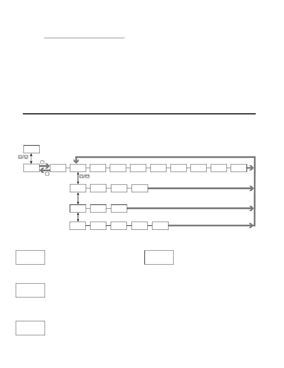
RATE INPUT PARAMETERS (
RAtE
)
This section details programming for the Rate indicators (A, B and C) and the Maximum and Minimum Rate Capture displays. For maximum input
frequency, the Rate indicators should be disabled when they are not in use. When Rate Enable (Rate A and B) or Rate Calculation (Rate C) is set to NO or NONE,
the remaining related parameters are not accessible. In the display depictions shown in this section, “x” represents A or B for the rate indicator being
programmed.
RATE SELECTION
RAtE A
RAtE C
Hi-Lo
RAtE b
UPdAtE
Select the Rate parameters to be programmed.
RATE ENABLE
NO
YES
Select YES to measure the rate (speed) of pulses on the corresponding Input.
Rate measurement is independent of the corresponding Counter count modes.
RATE DECIMAL POSITION
0
0.00
0.0000
0.0
0.000
This selects the decimal point position for the selected Rate indicator.
RATE SCALING POINTS
2
to
10
This parameter sets the number of scaling points for the Rate Scaling
function. The number of scaling points used depends on the linearity of the
process and the display accuracy required.
About Scaling Points
Each scaling point is specified by two programmable parameters: A desired
Rate Display Value (Rx dSP) and a corresponding Rate Input Value (Rx INP).
Scaling points are entered sequentially in ascending order of Rate Input value.
Each scaling point defines the upper endpoint of a linear segment, with the lower
endpoint being the previous scaling point.
Linear Application – 2 Scaling Points
Linear processes use two scaling points to provide a linear Rate display from
0 up to the maximum input frequency. For typical zero based frequency
measurements, the lower point is set to display 0 for 0 Hz input (factory setting)
and the upper point set to display the desired value for a given input frequency.
For non-zero based applications, the lower point is set to the desired display for
0 Hz input.
SELECt
RAtE A
Rt
RAtE
X
NO
Rt
x
dEC Pt
0
Rt
x
SC PtS
2
Rt
x