Code, Inp a, Inp b – Red Lion PAX2D User Manual
Page 30: Offset, Reset, Factry ), Actory, Ervice, Perations
30
f
aCTOry
s
erviCe
O
peraTiOns
(FACtrY)
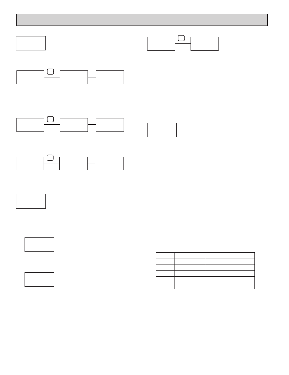
FACTORY SERVICE CODE
0-250
Enter the Service Code for the desired operation.
RESTORE FACTORY DEFAULTS
Use the ! and @ keys to display COdE 66 and press
P. The meter will flash
rESEt
and then return to COdE 50. Press the
P key to return to Display Mode.
This will overwrite all user settings with the factory settings. The only exception
is the User Mnemonics which retain their programmed values (see Code 69).
RESTORE FACTORY DEFAULTS (w/Units Mnemonics)
Same as Code 66, except the User Mnemonics are also returned to the factory
default settings (blank).
MODEL AND CODE VERSION
The meter will briefly display the model (P2d) on Line 1, and the current
firmware version (UEr x.xx) on Line 2, and then return to COdE 50.
INPUT A AND B LOGIC SELECTION
The Count Inputs A and B are factory configured for falling edge triggered
(active low) operation in single edge count modes. The Counter Operating Mode
descriptions in the Input programming section reflect this logic. If an application
is better suited to use rising edge triggered (active high) operation, the Input
Logic for Input A and/or Input B can be changed by entering Code 55.
LO-ACt HI-ACt
Selecting HI-ACt sets the Input A logic to rising edge triggered (active high)
operation. Be advised that all references to Input A falling edge and Input A
rising edge will be reversed for the Counter Operating Mode descriptions.
LO-ACt HI-ACt
Selecting HI-ACt sets the Input B logic to rising edge triggered (active high)
operation. Be advised that all references to Input B falling edge and Input B
rising edge will be reversed for the Counter Operating Mode descriptions.
METER CALIBRATION
NO RAtE AnLOut
Enter Code 48 and choose Rate or Analog Output calibration.
The only items in the PAX2D meter that can be calibrated are the Rate
Indicator accuracy and the Analog Output. The Rate Indicator is scaled in the
Rate Input Parameter programming section. The Analog Output signal is scaled
in the Analog Output Parameter section. If the Rate display or the Analog Output
appears to be indicating incorrectly or inaccurately, refer to the Troubleshooting
section to make sure the meter is properly scaled for the application.
If Rate accuracy or Analog Output recalibration is required (generally every
2 years), it should be performed by qualified technicians using appropriate
equipment. Calibration does not change any user programmed parameters.
Note: Allow a 30 minute warm-up period before staring calibration.
Rate Accuracy Calibration
-0.0100
to
0.0100
percent
Rate Indicator calibration is done by adjusting the Rate Accuracy Offset
value. This value provides a Rate calculation adjustment factor expressed in
percent of the display reading. An adjustment range of ± 0.01% is provided,
which equals ± 1 count for a display reading of 10,000.
The initial offset value is set during factory test. To calibrate, connect a
precision signal generator with an accuracy of 0.005% or better to Input A on the
PAX2D. (Refer to the Rate Input Parameter programming section for Rate setup
details.) Using the Rate A Decimal Point position and Scaling Display
parameters, program the meter to read the input frequency with maximum
display resolution (i.e. 6-digit display reading). Compare the Rate display to the
signal generator output frequency. Adjust the Rate Accuracy Offset value higher
(for low Display reading) or lower (for high Display Reading) until the Rate
display matches the signal generator.
Analog Output Card Calibration
Before starting, verify that a precision meter with an accuracy of 0.05% or
better (voltmeter for voltage output and/or current meter for current output) is
connected and ready. Using the chart below, step through the five selections to
be calibrated. At each prompt, use the PAX2D ! and @ keys to adjust the
output so that the external meter display matches the selection being calibrated.
When the external reading matches, or if the range is not being calibrated, press
the
P key to advance to the next range. When all the desired ranges have been
calibrated, exit programming mode and remove the external meters.
DISPLAY
EXTERNAL METER
ACTION
0.000A
0.00 mA
Adjust if necessary, press
P
0.004A
4.00 mA
Adjust if necessary, press
P
0.020A
20.00 mA
Adjust if necessary, press
P
0.0v
0.00 V
Adjust if necessary, press
P
10.0v
10.00 V
Adjust if necessary, press
P
COdE
5O
FCS
COdE
66
FCS
rESEt
COdE
50
FCS
P
COdE
69
FCS
rESEt
COdE
50
FCS
P
COdE
51
FCS
P2d
V Er
x.xx
FCS
COdE
50
FCS
P
COdE
55
FCS
INP A
LO-ACt
LOG
INP b
LO-ACt
LOG
COdE
48
FCS
CAL
NO
FCS
P
OFFSEt
0.0080
Pct