Figure 40, Relay module, Warning – Vaisala DMT340 User Manual
Page 61
Chapter 3 ________________________________________________________________ Installation
VAISALA ________________________________________________________________________ 59
0503-037
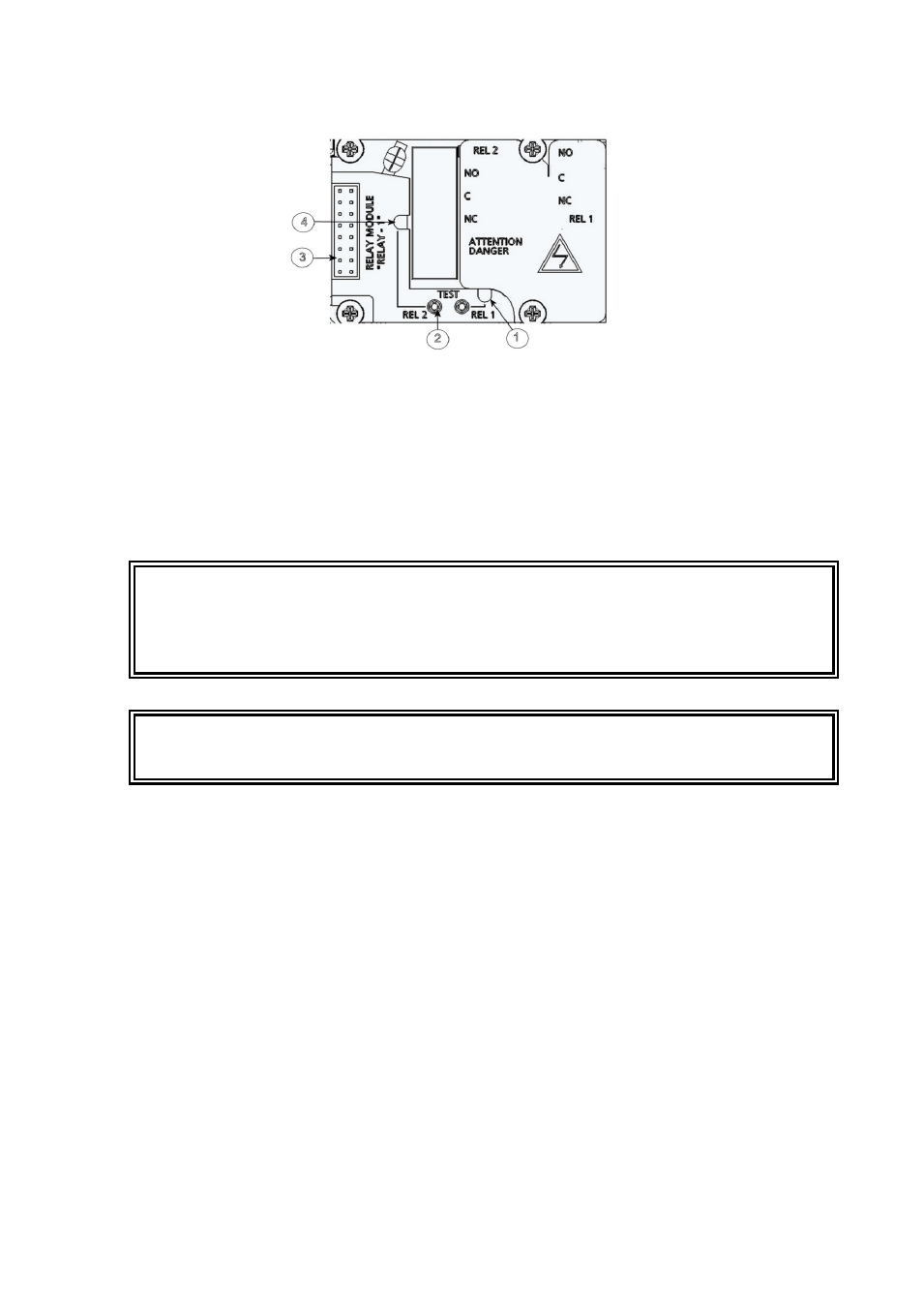
Figure 40
Relay Module
The numbers refer to Figure 40 above:
1
=
Indication led for the relay 1 or 3
2
=
Relay test buttons
3
=
Flat cable pins
4
=
Indication led for relay 2 or 4
WARNING
The relay module may contain dangerous voltages even if the
transmitter power has been disconnected. Before working on the relay
module you must switch off both the transmitter and the voltage
connected to the relay terminals.
WARNING
Do not connect the mains power to relay unit without grounding the
transmitter.
See also other documents in the category Vaisala Tools:
- DM500 (138 pages)
- DM70 (93 pages)
- DMT132 (74 pages)
- DMT143 (76 pages)
- DMT152 (70 pages)
- DMT242 (4 pages)
- DMT345 (185 pages)
- DPT145 (63 pages)
- DPT146 (71 pages)
- PTU300 (217 pages)
- PTB330TS (89 pages)
- PTB220 (10 pages)
- PTB220 (113 pages)
- PTB330 (144 pages)
- PTU200 (64 pages)
- PTU200MIK1 (18 pages)
- SPH10 (2 pages)
- SPH20 (2 pages)
- PTB110 (4 pages)
- PTB200 (30 pages)
- PTB210 (analog) (27 pages)
- PTB210 (serial) (32 pages)
- GM70 (68 pages)
- GMD20 (4 pages)
- GMK220 (18 pages)
- GML20 (2 pages)
- GML20T (2 pages)
- GMM20W (5 pages)
- GMM220 (6 pages)
- GMP231 (2 pages)
- GMP231 (90 pages)
- GMP343 (94 pages)
- GMR20 (2 pages)
- GMT220 (42 pages)
- GMW90 (101 pages)
- XMW90 (4 pages)
- MM70 (67 pages)
- MM70 (71 pages)
- MMT162 (66 pages)
- MMT310 (81 pages)
- MMT330 (181 pages)
- MMT330 (171 pages)