Transmitter housing grounding, Signal and power supply wiring, Figure 17 – Vaisala DMT340 User Manual
Page 34: Screw terminal block on the motherboard
User's Guide _______________________________________________________________________
32 ___________________________________________________________________ M210704EN-G
Transmitter Housing Grounding
In case you need to ground the transmitter housing, the grounding
connector is found inside the housing; see Figure 1 on page 20. Note
anyhow that the probe is connected to the same potential as the housing.
Make sure that different groundings are made to the same potential.
Otherwise harmful ground currents may be generated.
If it is needed to have galvanic isolation of the power supply line from
the output signals, DMT340 can be ordered with optional galvanic
isolation module.This module prevents harmful grounding loops.
Signal and Power Supply Wiring
When connecting transmitter with 8-pin connector, see section 8-Pin
Connector on page 68.
0605-028
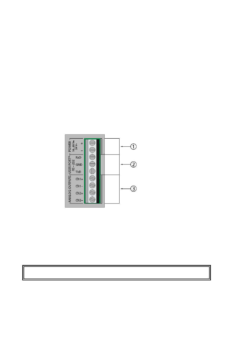
Figure 17
Screw Terminal Block on the Motherboard
The numbers refer to Figure 17 above:
1
=
Power supply terminals 10 ... 35 VDC, 24 VAC
2
=
User port (RS-232 terminals)
3
=
Analog signal terminals
WARNING
Make sure that you connect only de-energized wires.