Setting the relay outputs, Figure 71, Relay availability – Vaisala DMT340 User Manual
Page 135
Chapter 4 _________________________________________________________________ Operation
VAISALA _______________________________________________________________________ 133
Setting the Relay Outputs
NOTE
When you have only one relay module installed, its relays are called
“relay 1” and “relay 2”.
When you have two relay modules, the relays of the module connected
to slot MODULE 1 are called “relay 1” and “relay 2” and relays
connected to slot MODULE 2 are called “relay 3” and “relay 4”.
0706-013
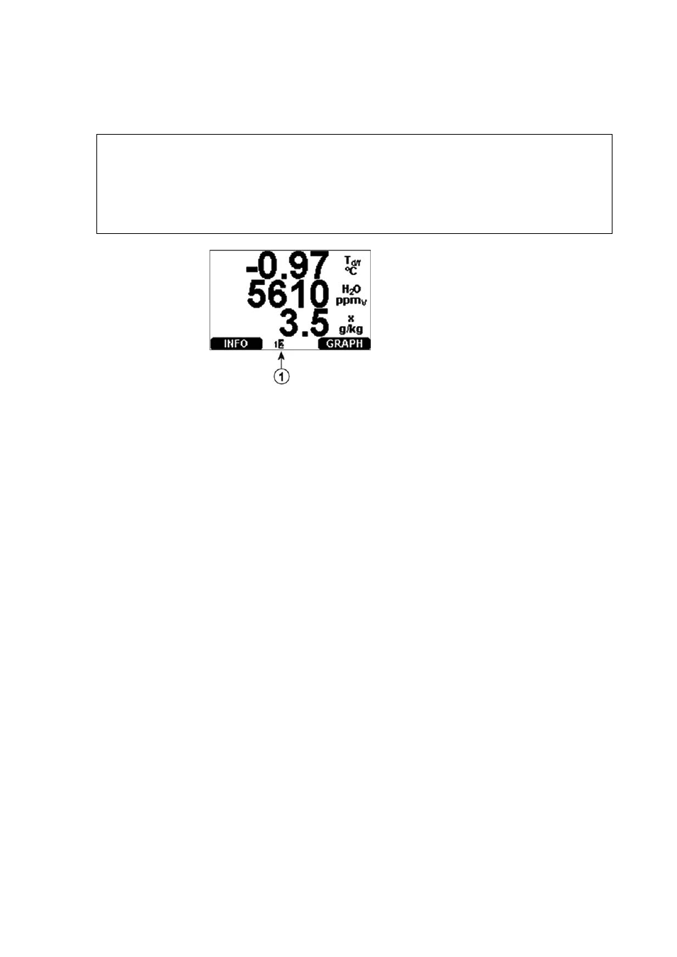
Figure 71
Relay Availability
Number refers to Figure 71 above:
1
=
Lists enabled relays. Activation state shown in black. Disabled
relays are not shown.
Use the display/keypad to set the relay outputs.
1.
Press any of the arrow buttons to open the Main Menu.
2.
Select Interfaces
, confirm by pressing the ►arrow button.
3.
Select Relay outputs
, confirm by pressing the ►arrow button.
4.
Select Relay 1/2/3/4
, confirm by pressing the ►arrow button.
5.
Select the Quantity, confirm by pressing Change. Select the
Quantity by using the arrow buttons. Confirm your selection by
pressing Select. (Press Fault Status when the relay follows the
transmitter error.) Press Change to to set the value.
6.
Select Act. above / Act. below. Press SET to confirm your
selection. If asked, select MODIFY if you want to set the setpoint
by using the arrow buttons. Select REMOVE if you want to
remove the setpoint.
7.
Select Hysteresis Press SET. Set the hysteresis by using the arrow
buttons. Press OK.
8.
Select Relay enable, press ON/OFF to enable/disable the relay.