American Fibertek SM10p-PoE User Manual
Page 117
¢
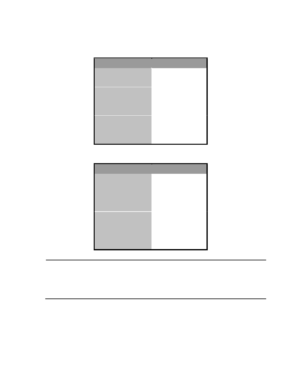
Pin out of POE Midspan Hub/Switch
Pin
1
2
3
4
5
6
7
8
¢
Pin out of POE Endspan Hub/Switch
Pin
1
2
3
4
5
6
7
8
Signal / Name
RX+
RX-
TX+
VCC+
VCC+
TX-
VCC-
VCC-
Signal / Name
TX+/VCC+
TX-/VCC+
TX+/VCC-
TX-/VCC-
Note ‘+’ and ‘-‘ signs represent the polarity of the wires that make up each wire pair.
Before you powered PD, please check the RJ-45 connector pin assignment
follow IEEE802.3af standard, otherwise you may need change one of the
RJ-45 connector pin assignment, which attached with the UTP cable.
All ports on this switch support automatic MDI/MDI-X operation, you can use
straight-through cables for all network connections to PCs or servers, or to other
switches or hubs. In straight-through cable, pins 1, 2, 3 and 6, at one end of the cable,
110
- MR-81 (4 pages)
- MT-81 (4 pages)
- RR-81 (4 pages)
- MR-88 (4 pages)
- MT-88 (4 pages)
- MTX-81B (4 pages)
- RRX-81B (4 pages)
- MR-81SL (4 pages)
- MT-81SL (4 pages)
- RD-20D AFINETY (12 pages)
- DRBK-1 (4 pages)
- PSR-2 (4 pages)
- SR-20 (4 pages)
- SR-20 R (7 pages)
- SR-20D (4 pages)
- MTX-8406C (5 pages)
- MTX-8410C (8 pages)
- MTX-8410C-SL (8 pages)
- MTX-8423C (8 pages)
- MTX-8423C-SL (8 pages)
- MTX-8485C (12 pages)
- MTX-8485C-SL (12 pages)
- MTX-8489C (12 pages)
- MTX-8489C-SL (12 pages)
- MRT-880C-SL (4 pages)
- MRT-880C (4 pages)
- MRT-860SL (8 pages)
- MRT-860 (8 pages)
- RT-440C-SL (4 pages)
- RR-440C-SL (4 pages)
- MT-440C-SL (4 pages)
- MR-440C-SL (4 pages)
- MR-440C-E (4 pages)
- MT-440C-E (4 pages)
- RR-440C-E (4 pages)
- RT-440C-E (4 pages)
- MR-440C (4 pages)
- MT-440C (4 pages)
- RR-440C (4 pages)
- RT-440C (4 pages)
- MR-404C (4 pages)
- MT-404C (4 pages)
- RR-404C (4 pages)
- RT-404C (4 pages)
- MR-220C (4 pages)