Starting the mpx100/100b, The mpx100 port and led locations, Start the mpx100/100b – HP 3000 Enterprise Virtual Array User Manual
Page 48: Command view eva
Starting the mpx100/100b
To start the mpx100/100b:
1.
Attach the AC power cord to the mpx100/100b and the power distribution unit (PDU). Verify
that the mpx100’s/100b's System Power LED is illuminated.
The mpx100/100b runs a self-test and begins normal operation.
2.
Verify that the Heartbeat LED is blinking (once per second) and that the Input Fault LED is not illu-
minated.
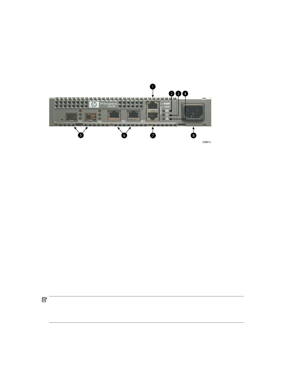
shows the location of the ports and LEDs on the mpx100/100b.
Figure 11 The mpx100 port and LED locations
.
2. Heartbeat LED
1. Management port (10/100 Ethernet)
4. System Fault LED
3. Input Power LED
6. iSCSI ports
5. FC ports
8. AC power
7. RS–232 port
Setting the mpx100/100b management port to use HP
StorageWorks Command View EVA
Communication between the mpx100/100b and HP Command View EVA is established through the
IP management port of the mpx100/100b and the IP connection of the HP Command View EVA
application server. This link is necessary for iSCSI device discovery and subsequent iSCSI settings of
the mpx100/100b through HP Command View EVA.
To set the mpx100/100b management port:
1.
Use Telnet to connect to the mpx100/100b management port, or connect to the mpx100/100b
serial port using the HP-supplied connector.
NOTE:
The mpx100/100b management port’s default IP address is 10.0.0.1/255.0.0.0. The
mpx100/100b serial port's default setting is 115200/8/n/1.
2.
Log in with the user name guest and the password password.
Installing and upgrading EVA iSCSI connectivity
48