Accton Technology VS4512DC User Manual
Page 89
VDSL Configuration
3-59
Noise margins should be configured to a level appropriate to the actual noise
level of the environment. A noisier environment requires a higher noise margin
to ensure a stable link. The noise margin only comes into effect after a link is
activated. Increasing the noise margin can result in the switch choosing a lower
profile. This will provide a link with a longer range but a lower data rate.
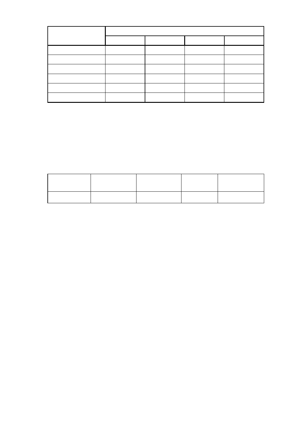
Example
The table below gives an example of a noise margin for a given profile and
theoretical minimum SNR.
Range; 0-9 dB. Default: 0 dB
• Interleave – Interleaving improves Reed-Solomon error correction when there
is pulse noise. A greater degree of interleaving will provide more protection
against pulse noise but will increase transmission delay and reduce the
effective bandwidth of the link. The degree of interleaving can be increased by
increasing the following parameters:
- M – The interleaving depth index.
Range: 0-64, Upstream default value: 8, Downstream default value: 16
- I – The interleaver block length.
Options: 4 or 8; Upstream default value: 8, Downstream default value: 8
A5-50-7
35
26
23
14
A6-22-3A
26
10
17
10
A7-40-5A
32
23
17
Not Used
A8-46-7A 35
26
23
14
TLAN 32
10
29
10
Max-Rate 41
41
41
41
Profile Name
Downstream
Rate (Mbps)
Upstream Rate
(Mbps)
SNR
Noise Margin
(dB)
S1-16-16
16.74
10
20
6
Profile Name
Theoretical Minimum Signal-to-Noise Ratio (dB)
DS1
DS2
US1
US2