Fresh air openings for confined spaces – A.O. Smith 3400 User Manual
Page 23
23
CONFINED SPACE
A confined space is one whose volume is less than 50 cubic
feet per 1,000 Btu/hr (4.8 cubic meters per kW) of the total input
rating of all appliances installed in the space.
Openings must be installed to provide fresh air for combustion,
ventilation and dilution in confined spaces. The required size for
the openings is dependent on the method used to provide fresh
air to the confined space and the total Btu/hr input rating of all
appliances installed in the space.
DIRECT VENT APPLIANCES
Appliances installed in a direct vent configuration that derive all
air for combustion from the outdoor atmosphere through sealed
intake air piping are not factored in the total appliance input Btu/
hr calculations used to determine the size of openings providing
fresh air into confined spaces.
EXHAUST FANS
Where exhaust fans are installed, additional air shall be provided
to replace the exhausted air. When an exhaust fan is installed
in the same space with a water heater, sufficient openings to
provide fresh air must be provided that accommodate the
requirements for all appliances in the room and the exhaust fan.
Undersized openings will cause air to be drawn into the room
through the water heater’s vent system causing poor combustion.
Sooting, serious damage to the water heater and the risk of fire
or explosion may result. It can also create a risk of asphyxiation.
LOUVERS AND GRILLES
The free areas of the fresh air openings in the instructions that
follow do not take in to account the presence of louvers, grilles or
screens in the openings.
The required size of openings for combustion, ventilation and
dilution air shall be based on the “net free area” of each opening.
Where the free area through a design of louver or grille or screen
is known, it shall be used in calculating the size of opening
required to provide the free area specified. Where the louver and
grille design and free area are not known, it shall be assumed
that wood louvers will have 25% free area and metal louvers and
grilles will have 75% free area. Non motorized louvers and grilles
shall be fixed in the open position.
FRESH AIR OPENINGS FOR CONFINED SPACES
The following instructions shall be used to calculate the size,
number and placement of openings providing fresh air for
combustion, ventilation and dilution in confined spaces. The
illustrations shown in this section of the manual are a reference
for the openings that provide fresh air into confined spaces
only. Do not refer to these illustrations for the purpose of vent
installation. See Venting section on Page 25 for complete venting
installation instructions.
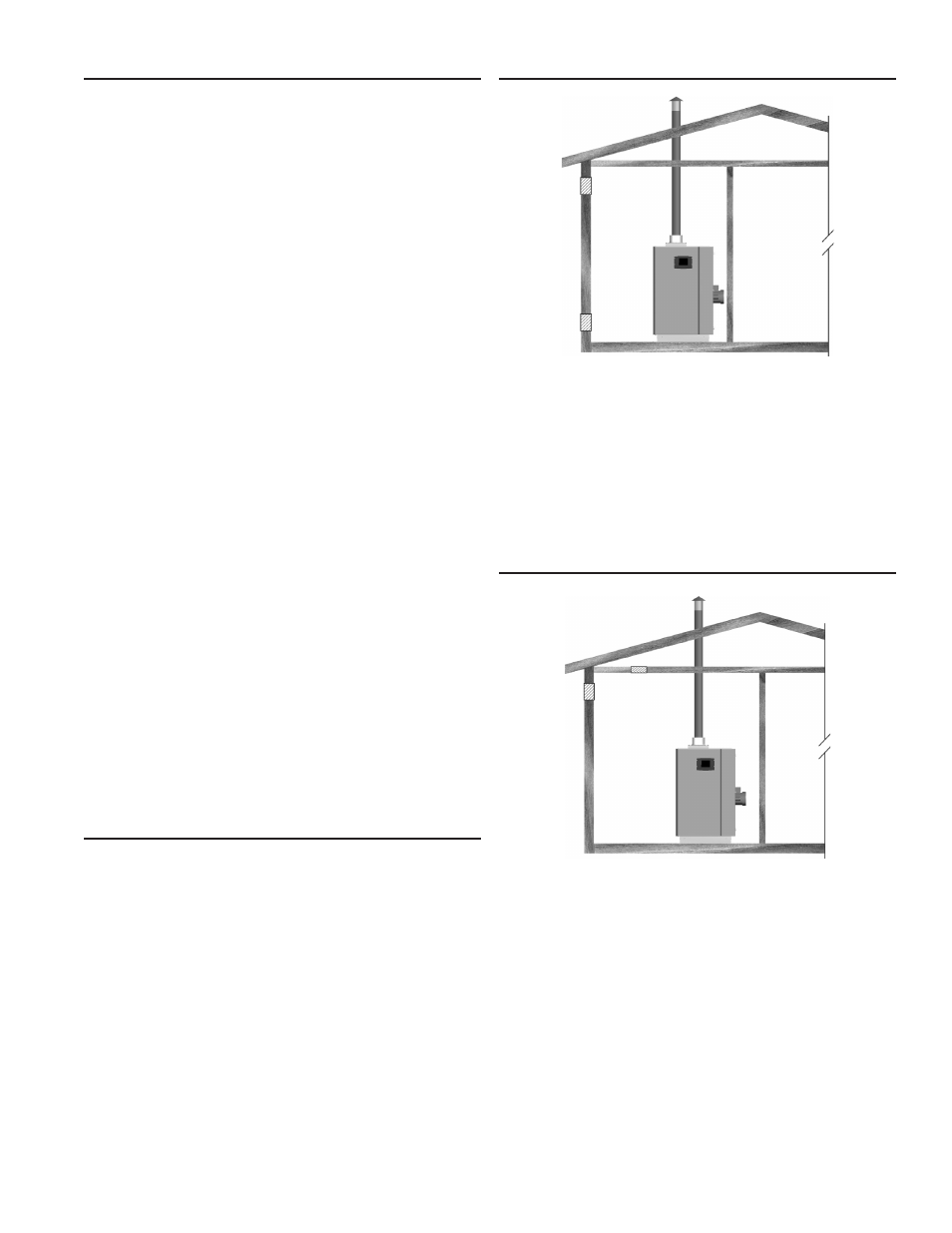
OUTDOOR AIR THROUGH TWO OPENINGS
The confined space shall be provided with two permanent
openings, one commencing within 12 inches (300 mm) of the top
and one commencing within 12 inches (300 mm) of the bottom of
the enclosure. The openings shall communicate directly with the
outdoors. See Figure 17.
Each opening shall have a minimum free area of 1 square inch
per 4,000 Btu/hr (550 mm
2
per kW) of the aggregate input rating
of all appliances installed in the enclosure. Each opening shall
not be less than 100 square inches (645 cm
2
).
OUTDOOR AIR THROUGH ONE OPENING
Alternatively a single permanent opening, commencing within 12
inches (300 mm) of the top of the enclosure, shall be provided.
See Figure 18. The water heater shall have clearances of at
least 1 inch (25 mm) from the sides and back and 6 inches (150
mm) from the front of the appliance. The opening shall directly
communicate with the outdoors or shall communicate through a
vertical or horizontal duct to the outdoors or spaces that freely
communicate with the outdoors and shall have a minimum free
area of the following:
1. 1 square inch per 3000 Btu/hr (700 mm
2
per kW) of the total
input rating of all appliances located in the enclosure, and
2. Not less than the sum of the areas of all vent connectors in
the space.
FIGURE 17. OUTDOOR AIR THROUGH TWO OPENINGS
FIGURE 18. OUTDOOR AIR THROUGH ONE OPENING