Installation instructions (s7999d oi display), Starting up the s7999d oi display – A.O. Smith 3400 User Manual
Page 49
49
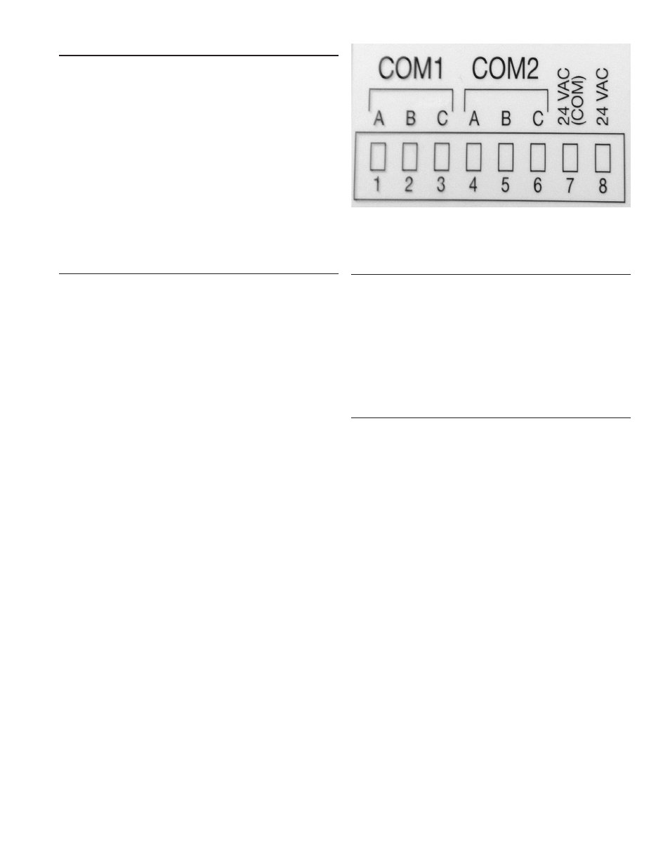
FIGURE 48. S7999D OI DISPLAY CONNECTOR TERMINALS
QUICK SETUP (S7999D OI DISPLAY)
1. Make sure the S7999D 8-pin connector is properly aligned
and pressed firmly in place.
2. Make sure the wires between the 8-pin connector and the
controller are properly wired and secured.
WARNING: Electrical Shock Hazard. It can cause severe injury,
death or equipment damage. Line voltage is present at the 120
VAC power supply.
3. Make sure the power supply is connected securely to the
120 VAC power source.
STARTING UP THE S7999D OI DISPLAY
POWER-UP VALIDATION
The Home page will appear when the device is properly powered.
Select the Setup button to adjust the contrast and sound as
desired.
If the screen is dim, check the pin 7 and 8 wiring connections.
A “camera” icon on the left top corner is for screen snapshot
use. Up to 16 snapshots can be stored in the display and can be
copied to a USB memory stick.
NOTE: An Advanced Startup screen displays for five seconds
after power-up before the Home page displays. This screen
allows the user to upgrade the software in the System Display
and should normally be bypassed.
Three LEDs exist for I/O traffic: one for the Ethernet network port
and two for Modbus™ ports. Modbus Com Port 2 is not active
on this device.
1. Make sure the Power and COM1 LEDs are blinking.
2. If the LEDs are not blinking:
• Make sure the proper connections have been made
between the Modbus COM1 Port and the first controller
device in the Modbus network.
• Ensure proper wiring of the OI Display 8-pin Header
Connections.
3. If connected to a BAS application, COM2 LED will blink
indicating BAS traffic.
SPECIFICATIONS
1. Electrical Ratings:
• Input Voltage: 18 – 30 Vac (24Vac nominal), 50/60 Hz
• Input Current: 500 mA max.
• Power consumption: 12W max.
2. Operating Temperature: -4 to 158 ºF (-20 to 70 ºC)
3. Storage/Shipping Temperature: -22 to 176 ºF (-30 to 80 ºC)
4. Humidity: 90% RH, non-condensing.
5. Enclosure rating: IP10 / NEMA 1
6. Approvals:
FCC Part 15, Class A Digital Device
Underwriter’s Laboratories, Inc. (UL) (cUL) Component
Recognized (for non-continuous operation): File Number
MH17367 (MJAT2, MJAT8).
INSTALLATION INSTRUCTIONS (S7999D OI DISPLAY)
The OI Display can be mounted on the door panel of an
electrical enclosure.
1. Select the location on the door panel to mount the display;
note that the device will extend into the enclosure at least
one inch past the mounting surface.
2. Provide an opening in the panel door 8" wide X 5 1/2" high
(for front panel mount) or 7 1/8" wide X 4 11/16" high (for
rear panel mount).
3. Place the OI Display in the opening and use it as a
template to mark the location of the four mounting screw
holes. Remove the device.
4. Using pilot holes as guides, drill 1/4 in. holes through the
door panel.
5. Place the display in the opening, aligning the mounting
holes in the device with the drilled holes in the panel.
6. Secure the display to the panel with four #6-32 screws and
nuts provided.
7. Wire the 24VAC power supply and the RS-485 cables.
8. Ensure the 8-pin connector plug is aligned with the header
pins when inserting the 8-pin connector plug back onto the
Display. Secure firmly.
9. Please make sure resistive spark cable is used with the
display system, and route the wires away from the display
as much as possible.