Control system, Burner control system – A.O. Smith 3400 User Manual
Page 45
45
4. 24VAC:
• Output control of gas control valve (Pilot and Main) and
External Ignition Transformer.
• Digital inputs for room limit control, high limit control, Gas
pressure switch, low water cutoff.
5. External spark transformer.
6. Flame Sensor.
7. Test jacks for flame signal measurement from a flame sensor.
8. Alarm Output.
COMMUNICATIONS AND DISPLAYS
Two modes of communications are available to the R7910.
1. The R7910 has two RS485 communication ports for
ModBus that allows for interfacing to one or all R7910s of
a system and presents them individually to the user. The
S7999D System Operator interface is a color touchscreen
display used for configuration and monitoring of the R7910A.
Though configuration can be done through the display, it is
not recommended as all the parameters are pre-configured
by the manufacturer. Any custom configuration required by
the field should be done in consultation with the A. O. Smith
qualified service technician. Control Operation and display
status in both test and graphical modes can be shown along
with the ability to setup. The R7910 can also be remotely
reset through the S7999D display.
2. Either ModBus RS485 communication port can be used to
allow configuration and status data to be read and written
to the R7910. Support a Master S7999D or a Building
Automation master to control the R7910 to respond to
a single ModBus address to service the requests of the
ModBus master in a Lead/Lag arrangement.
SPECIFICATIONS
1. Electrical Ratings:
Operating voltage
• 24VAC (20 to 30 VAC, 60 Hz ±5%)
• 30 amps (Single Heat Exchanger)
• 60 amps (Double Heat Exchanger)
Connected Load for Valve and annunciator functions:
• 24VAC, 60Hz
• 120VAC (+10%/-15%), 60Hz (±5%)
• Model Specific
2. Corrosion:
• R7910A must not be used in a corrosive environment.
3. Operating Temperature: -4°F to 150°F (-20°C to 66°C)
4. Storage/Shipping Temperature: -40°F to 150°F (-40°C to
66°C).
5. Humidity:
• Up to 95% Relative Humidity, noncondensing at 104°F for
14 days. Condensing moisture may cause safety shutdown.
6. Vibration: 0.0 to 0.5g Continuous (V2 level)
7. Enclosure: Nema 1/IP40.
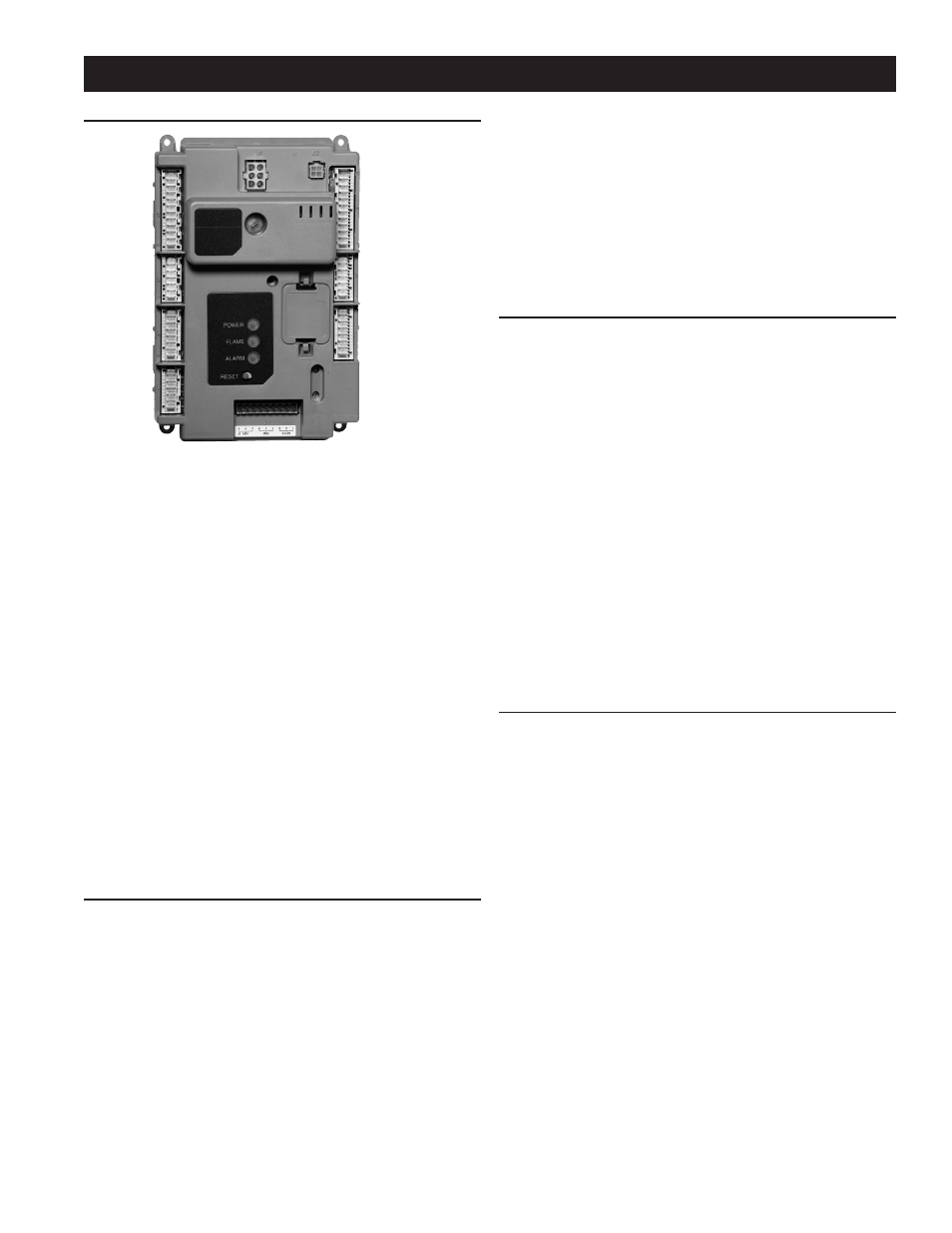
CONTROL SYSTEM
BURNER CONTROL SYSTEM
FIGURE 46. R7910A1138 CONTROL SYSTEM
The R7910A1138 is a burner control system that provide
heat control, flame supervision, circulation pump control,
fan control, boiler control sequencing, and electric ignition
function. It will also provide boiler status and error reporting.
Multiple boilers can be joined together to heat a system instead
of a single, larger burner or boiler. Using boilers in parallel is
more efficient, costs less, reduces emissions, improves load
control, and is more flexible than the traditional large boiler.
Control System consists of:
• R7910A1138 Control Device.
• S7999D Touchscreen Display—required for setup and
ModBus communication but not required for the system
to operate once the R7910A1138 is programmed.
• S7910A Local Keyboard Display Module.
• Flame Sensor .
• Temperature Sensor, NTC Type 10KΩ at 77°F (25°C) or
12KΩ at 77°F (25°C).
• Limit Sensor, NTC Type 10KΩ at 77°F (25°C).
• 24V Digital I/O.
OVERVIEW
Functions provided by the R7910A1138 include automatic boiler
sequencing, flame supervision, system status indication, firing
rate control, load control, CH/DHW control, limit control, system
or self-diagnostics and troubleshooting.
The R7910 maximum version of the controller offers:
1. NTC-temperature sensor for:
• Outlet Limit And Temperature.
• Stack Temperature Limit and Temperature.
• Inlet Temperature.
• Outdoor Temperature (R7910 only).
2. Modulating output PWM-driven rotation speed controlled
DC-fan for optimal modulation control.
3. Three Pump Outputs with 5 selectable operation modes.