A.O. Smith 3400 User Manual
Page 67
67
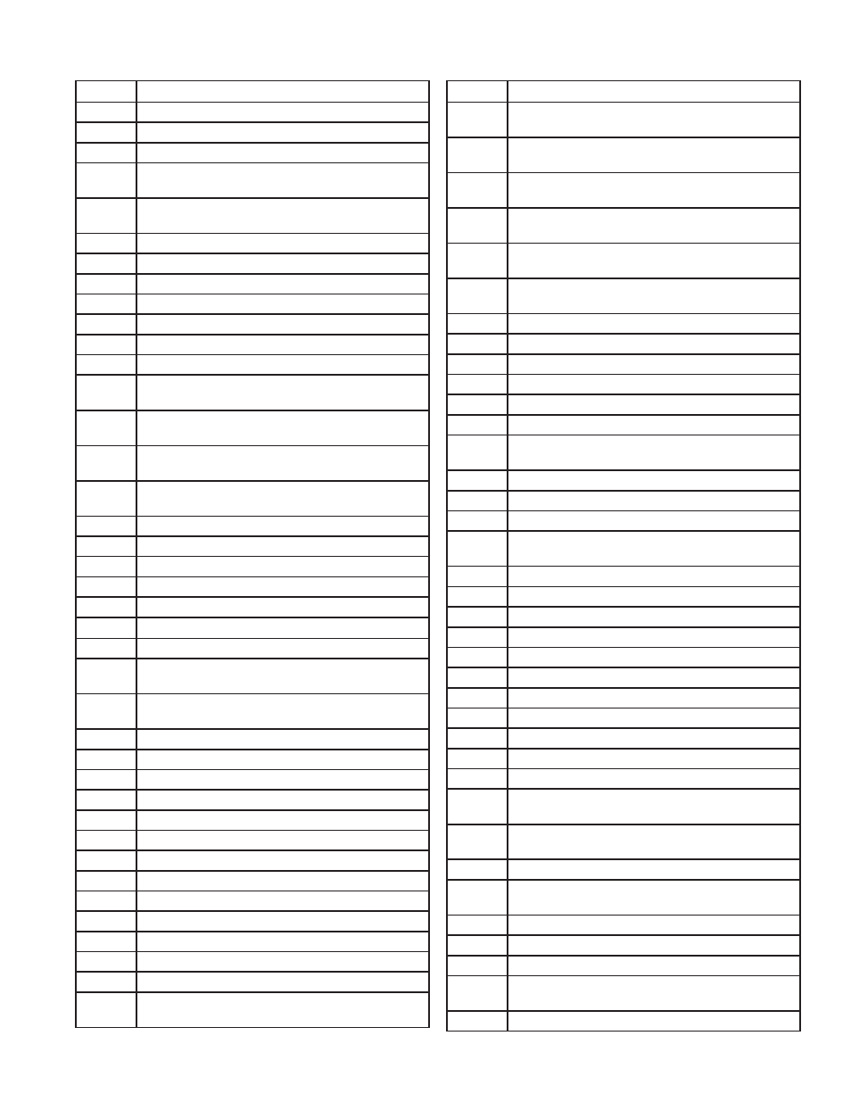
CODE
DESCRIPTION
37
Program Module application parameter revision
differs from application processor
38
Program Module safety parameter revision differs
from safety processor
39
PCB incompatible with product contained in
Program Module
40
Parameter PCB in Program Module is too large for
product
41
Range PCB in Program Module was too large for
product
42
Alert PCB in Program Module was too large for
product
43
IAS start check was forced on due to IAS enabled
System Operation Faults
44
Low voltage was detected in safety processor
45
High line frequency occurred
46
Low line frequency occurred
47
Invalid subsystem reset request occurred
48
Write large enumerated Modbus register value
was not allowed
49
Maximum cycle count was reached
50
Maximum hours count was reached
51
Illegal Modbus write was attempted
52
Modbus write attempt was rejected (NOT
ALLOWED)
53
Illegal Modbus read was attempted
54
Safety processor brown-out reset occurred
55
Application processor watchdog reset occurred
56
Application processor brown-out reset occurred
57
Safety processor watchdog reset occurred
58
Alarm was reset by the user at the control
Demand/Rate Command Faults
59
Burner control firing rate was > absolute max rate
60
Burner control firing rate was < absolute min rate
61
Burner control firing rate was invalid, % vs. RPM
62
Burner control was firing with no fan request
63
Burner control rate (nonfiring) was > absolute max
rate
64
Burner control rate (nonfiring) was < absolute min
rate
65
Burner control rate (nonfiring) was absent
66
Burner control rate (nonfiring) was invalid, %
vs.RPM
67
Fan off cycle rate was invalid, % vs. RPM
68
Setpoint was overridden due to sensor fault
69
Modulation was overridden due to sensor fault
70
No demand source was set due to demand priority
conflicts
71-73
RESERVED
CODE
DESCRIPTION
EE Management Faults
0
None (No alert)
1
Alert PCB was restored from factory defaults
2
Safety configuration parameters were restored
from factory defaults
3
Configuration parameters were restored from
factory defaults
4
Invalid Factory Invisibility PCB was detected
5
Invalid Factory Range PCB was detected
6
Invalid range PCB record has been dropped
7
EEPROM lockout history was initialized
8
Switched application annunciation data blocks
9
Switched application configuration data blocks
10
Configuration was restored from factory defaults
11
Backup configuration settings was restored from
active configuration
12
Annunciation configuration was restored from
factory defaults
13
Annunciation configuration was restored from
backup
14
Safety group verification table was restored from
factory defaults
15
Safety group verification table was updated
16
Invalid Parameter PCB was detected
17
Invalid Range PCB was detected
System Parameter Errors
18
Alarm silence time exceeded maximum
19
Invalid safety group verification table was detected
20
Backdoor Password could not be determined
21
Invalid safety group verification table was not
accepted
22
CRC errors were found in application configuration
data blocks
23
Backup Alert PCB was restored from active one
24
RESERVED
25
Lead Lag operation switch was turned OFF
26
Lead Lag operation switch was turned ON
27
Safety processor was reset
28
Application processor was reset
29
Burner switch was turned OFF
30
Burner switch was turned ON
31
Program Module (PM) was inserted into socket
32
Program Module (PM) was removed from socket
33
Alert PCB was configured
34
Parameter PCB was configured
35
Range PCB was configured
36
Program Module (PM) incompatible with product
was inserted into socket
TABLE 23. ALERTS